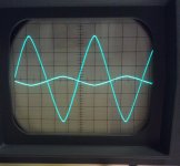
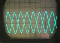
Is this the expected output signal from an Aleph P ?
I've completed the built so far. Started measuring on it.
Output signals look okay, but the level looks odd.
I've grounded the negative input, as i only use unbalanced sources.
Want to use balanced output to drive my Aleph J.
These signals look a lot like the BoSoZ output. I expected more symetrical signals.
So question to other builders, does my signal output look okay ?
The fets and ztx devices were matched, but not on microvolt level")
Regards,
Nick
I've completed the built so far. Started measuring on it.
Output signals look okay, but the level looks odd.
I've grounded the negative input, as i only use unbalanced sources.
Want to use balanced output to drive my Aleph J.
These signals look a lot like the BoSoZ output. I expected more symetrical signals.
So question to other builders, does my signal output look okay ?
The fets and ztx devices were matched, but not on microvolt level
Regards,
Nick
Attachments
Awesome! Mine took about six weeks to break in, was a little edgy for a while and than that disappeared completely. Let us know what happens with yours in that regard... I used the same Panasonic film caps that were used in the factory versions. That may explain my long break in period. But I am very happy with how it sounds now.
Mark
Mark
I have two question for our friend Zen Mod ...
Is it save to use to use 63V (22mm) on the P 1.7 ?
I'm only asking because the 100V (25mm) ones don't fit in the board (acaudio.de).
To use 18mm ones I have make some new holes and I really don't want to do that but...
What is the recommended dummy load to test the power supply?
Regards
Is it save to use to use 63V (22mm) on the P 1.7 ?
I'm only asking because the 100V (25mm) ones don't fit in the board (acaudio.de).
To use 18mm ones I have make some new holes and I really don't want to do that but...
What is the recommended dummy load to test the power supply?
Regards
oh boy ..... juggling through myriad (old) projects ...... I'm not so young anymore and my memory wasn't so good even when I was 
so , according to http://www.diyaudio.com/forums/pass...1-7-preamp-builders-thread-8.html#post4018045 , say that you can count on dummy load calculated for 70-80mA per channel
that would be R=U/I = 60V/80mA=750R
dissipation will be P=I^2 x R =4.8W , so you need to use at least 10W resistor , or resistor group
all that counting that you'll test complete PSU , with reg and dummy load on reg's output
63V caps , even at regulated rail , are way too close to trouble
you must go for higher voltage ones
Thanks ZM
I was not expecting this answer but something shorter.
Is there any other option to the 750 ohms resistor, I have some 25W ones but not this value.
Going to rebuild the power supply board just found out I have all the diodes/zenners in the wrong position ( I printed the top screen the wrong way around) and order the 750r power resistor.
Thanks
Small update...
Power supplies (2) fixed, tested and running.
With the bulb tester connected I have 59.1V on both supplies with 740 ohm dummy load (was the closest I cold get with 10W resistor).
Now it's time to go finnish the preamp board just need to match the mosfets and find some replacements for the ztx450/550.
Thaks ZM for the info on the dummy load
ztx450/550 replacement
Ok, my local supplier is a waste os time.
I have this options in my parts bin.
ZTX450 - 60V - 1A - 1W - NPN ---- original Tr (10)
ZTX550 - 60V - 1A - 1W - PNP ---- original Tr (NA)
BC546 - 65V - 0.1 - 0.5W - NPN -- 5
BC556 - 65V - 0.1 - 0.5W - PNP -- NA
2SA733 - 60V - 0.1 - 0.25W - PNP -- 8
2SC945 - 60V - 0.1 - 0.25W - NPN -- 6
BC639 - 100V - 1A - 0.8W - NPN -- 10
BC640 - 100V 1.5A - 0.8W - PNP -- 10
MPSA42 - 300V - 0.5W - 0.625W -- 10
MPSA92 - 300V - 0.5W - 0.625W -- 10
I know about the different pinout but that is not a problem
Planing on going with the BC639/640 unless someone tells me otherwise.
Just one question can I power up the preamp board without heatsink on the mosfets ?
Back to the bench
Last edited:
Hi all
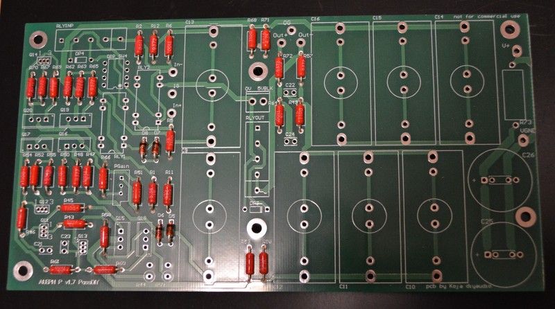
I have start to build Aleph P1.7 with Koja PCB but have some question ;
I need a plain version to drive Aleph X and Aleph mini (XLR), and the source will be AYA II DAC (SE).
So could someone tell me what ohmit on PCB to get plain version of P1.7
I don't need no extra outputs or so...
I don't know the use for RLYINP, RLYOUT...
How to ohmit DIP SW4 and RLY1 and RLY2 ?
why do we need tham at first place ?
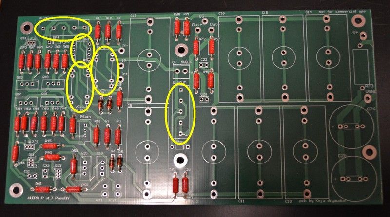
Here is the PCB look and it would be great if someone could draw what to ohmit on it (if that's not to much to ask...I believe it is , but any way )
I have start to build Aleph P1.7 with Koja PCB but have some question ;
I need a plain version to drive Aleph X and Aleph mini (XLR), and the source will be AYA II DAC (SE).
So could someone tell me what ohmit on PCB to get plain version of P1.7
I don't need no extra outputs or so...
I don't know the use for RLYINP, RLYOUT...
How to ohmit DIP SW4 and RLY1 and RLY2 ?
why do we need tham at first place ?
Here is the PCB look and it would be great if someone could draw what to ohmit on it
(if that's not to much to ask...I believe it is , but any way )

Last edited:


- Home
- Amplifiers
- Pass Labs
- Pass Aleph P 1.7 preamp builders thread