If I can suggest the next step is to find a pair of 470pF capacitors...
To be clear - one 470pF cap for each 1541A chip - and link pins 16 on each chip together - with no other connections to anywhere.. matched caps at 470pF will be best. This will have fDEM at 176kHz which is 4x the 44.1kHz sampling rate which is what you want.
Again - if it works it works, if it doesnt the problem is NOT with the DEM cct.
Once you get the parallel combination working, you have a benchmark and from there you can try other more elaborate DEM schemes knowing that any problem is resultant on the most recent change = very important.
LH/S
I didn't have another 470pf for the other dac, but now have used two pairs of Nichicon 1n in series and pins 16 linked.
Success - no noise or other nasties when paralleled just that smooth 1541 sound free from grain and glare.
I do still want to try driving the dem oscillator inputs with 176Khz or 352Khz derived from the bit clock as per ecdesigns & others, although I'll be surprised if I can hear any improvement.
Many thanks for your input.
Ian
Attachments
Success - no noise or other nasties when paralleled just that smooth 1541 sound free from grain and glare.
I do still want to try driving the dem oscillator inputs with 176Khz or 352Khz derived from the bit clock as per ecdesigns & others, although I'll be surprised if I can hear any improvement.
Many thanks for your input.
Ian
Excellent.. ;-)
IIRC Ecdesigns most recent design (evolution?) simply ties each end of that capacitor to -15V with a couple of 6k8 resistors - easy to try.
LH/S
I have used a rather large mica capacitor of 470 pF, and though having a large footprint it worked very well (at my NOS frequencies). 2 cnts.If I can suggest the next step is to find a pair of 470pF capacitors...
LH/S
If I can suggest the next step is to find a pair of 470pF capacitors...
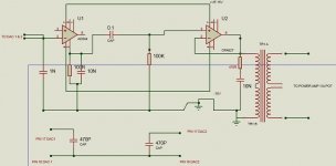
To be clear - one 470pF cap for each 1541A chip - and link pins 16 on each chip together - with no other connections to anywhere.. matched caps at 470pF will be best. This will have fDEM at 176kHz which is 4x the 44.1kHz sampling rate which is what you want.
LH/S
With two 1nf in series on each dac, the dem clocks are around 220khz and not stable but I can't do any more testing until I fix the 5v supply and assuming it didn't take the 5v chips & dacs with it when it blew.
.. matched caps at 470pF will be best. This will have fDEM at 176kHz which is 4x the 44.1kHz sampling rate which is what you want.
LH/S
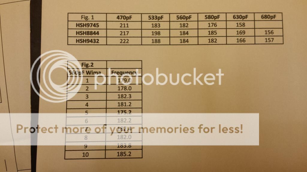
A few years ago I did some measurements to see how the DEM cap value changed the DEM frequency inside my Arcam Alpha 5 CD player. Here are the results I got:

The top table shows the DEM frequency for different TDA1541A chips and different DEM cap values.
The lower table shows results I got from a bag of 10x Wima 560pF caps (I think they were 5% tolerance IIRC).
When taking these measurements I found that it takes several minutes for the frequency to stabilise (presumably due temperature stabilisation?).
I now run 560pF in my own modified CD player as this seems to get me closest to 176kHz.
My subjective listening impressions are that anything in the 470pF to 680pF range sounds OK.
Last edited:
A few years ago I did some measurements to see how the DEM cap value changed the DEM frequency inside my Arcam Alpha 5 CD player. Here are the results I got:
The top table shows the DEM frequency for different TDA1541A chips and different DEM cap values.
The lower table shows results I got from a bag of 10x Wima 560pF caps (I think they were 5% tolerance IIRC).
When taking these measurements I found that it takes several minutes for the frequency to stabilise (presumably due temperature stabilisation?).
I now run 560pF in my own modified CD player as this seems to get me closest to 176kHz.
My subjective listening impressions are that anything in the 470pF to 680pF sounds OK.
I am wondering if I can sync the dem clock to bck by injecting 176khz via a cap of say 100pf into pin 16. (leaving the existing 470pf cap in place but increasing it to 560p)
There is an HC161 counter/divider onboard the dac connected to bck so there are a range of frequencies I can try, but the 176khz output seems the obvious one.
If this doesn't work I'll try the reclocking methods.
If I can't hear any improvement I'll just stick with 560pf.
Linking the dac's pin 16s has cured the noise when the dac outputs were paralleled but not 100% reliably (may be temperature related)
I am wondering if I can sync the dem clock to bck by injecting 176khz via a cap of say 100pf into pin 16. (leaving the existing 470pf cap in place but increasing it to 560p)
better to synch to master clock, divide down by either 64 or 128 series 10k resistor + 100nF series cap to pin 17, remove cap across 16,17 completely, pin 16 to ground via 100nF cap ?
LH/S
I tried to sync the DEM clock to an external reference, but it did not work. If anybody knows a tried and working method to sync it to BCK, please share it.better to synch to master clock, divide down by either 64 or 128 series 10k resistor + 100nF series cap to pin 17, remove cap across 16,17 completely, pin 16 to ground via 100nF cap ?
BTW for me 510 pF gave 176.4 kHz free running DEM clock.
I tried to sync the DEM clock to an external reference, but it did not work. If anybody knows a tried and working method to sync it to BCK, please share it.
BTW for me 510 pF gave 176.4 kHz free running DEM clock.
There are several ways to do this by dividing it down to 176, 352Khz or higher.
Search for 'dem reclocking'.
It seems that you need to disable the dem oscillator, although I would have thought it possible to get it running at about 176 first and then feeding in via a 100n cap & 10k resistor to pin 16, 176khz from bck + divider to synchronise it.
You can apparently disable the oscillator with 2k2 to -15v on pins 16 & 17 (remove the 510pf as well) and then drive the pins in antiphase via 10k resistors, or possibly with 10k + 100n caps in series.
Some have used 7474 flip flops, others a divider + an inverter to provide the inverted clock.
The Grundig method is another if you are using 4xOS and is also the simplest
because wsclk is 176Khz so no dividers or inverters needed.
With nos, wsclk is 44Khz - too low for dem reclocking so you do need to divide bck or your master clock.
Thanks batteryman, this I will try. The method that never worked for me is to pull the free running DEM clock to a multiple frequency accurate clock. Like a PLL, using some hypothetical "internal crosstalk" effect...
No, I can't see it syncing to a multiple so doubt that internal crosstalk will do anything other than cause the dem clock frequency to wander about.
Of course syncing it may not work very well either so you may have to disable it and inject from divided bck.
Ian
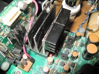
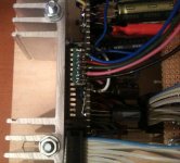
Finally somebody suggested it! I use 2 heatsinks like on the picture, it is a must!One important thing is to mount big heatsink on TDA1541A. Try and listen. Temperature matters, measure and compare T with and without heatsink.
Attachments
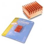
One important thing is to mount big heatsink on TDA1541A. Try and listen. Temperature matters, measure and compare T with and without heatsink.
Yes I'll be doing this when my new dac kit is delivered.
I tried to sync the DEM clock to an external reference, but it did not work. If anybody knows a tried and working method to sync it to BCK, please share it.
BTW for me 510 pF gave 176.4 kHz free running DEM clock.
As posted previous with the divide down works with either BCK or MCK.
I wonder if you could use a synchronous multiplier (x4) with WS for non-oversampling ??
Agree about the heatsink, could even connect to signal common or main earth.
LH/S
Attachments
I've just realised I posted a complaint in July 2011 about this Raindrop hui dual 1541dac that I'd just received.
It was making the same noise then but I knew nothing about dem clocks so never thought to add the capacitor across pins 16-17.
Instead I just removed one of the dacs!
If I'd known then what I know now...!
It was making the same noise then but I knew nothing about dem clocks so never thought to add the capacitor across pins 16-17.
Instead I just removed one of the dacs!
If I'd known then what I know now...!
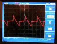
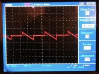
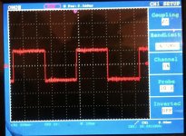
Here is some pics BUT with TDA1540 chip. I think that some of that could be valid way for the TDA1541A too?
for instance i measured about 140KHz at the DEM pins with original value of Cdem.
But with free running DEM and each pin connected via R=20K to -18V power pin (measured 200uA cca. each R)
dem F reaches 170KHz...
Also I mount each channel chip on grounded heatsink.")
...
look at the 20KHz square at the output
for instance i measured about 140KHz at the DEM pins with original value of Cdem.
But with free running DEM and each pin connected via R=20K to -18V power pin (measured 200uA cca. each R)
dem F reaches 170KHz...
Also I mount each channel chip on grounded heatsink.
...
look at the 20KHz square at the output
Attachments
- Status
- This old topic is closed. If you want to reopen this topic, contact a moderator using the "Report Post" button.
- Home
- Source & Line
- Digital Source
- Parallel TDA1541A DAC Noise