Here is some pics BUT with TDA1540 chip. I think that some of that could be valid way for the TDA1541A too?
for instance i measured about 140KHz at the DEM pins with original value of Cdem.
But with free running DEM and each pin connected via R=20K to -18V power pin (measured 200uA cca. each R)
dem F reaches 170KHz...
Also I mount each channel chip on grounded heatsink.
...
look at the 20KHz square at the output
http://www.diyaudio.com/forums/digi...ding-ultimate-nos-dac-using-tda1541a-506.html
check out posts #5059 - and then #5060 at the bottom of the linked page. Probably explains everything.
LH/S
Yes that link is more appropriate to this topic for tda1541A?
I tested same aproach on bit different chip like i said it was tda1540, with generator from computer and then measured...
Not sure about tda1540, I dont know much about it.. the linked post illustrates the difference between analog and digital oscilloscopes and the way some of them display the info. After the resistors to -15V the digital screen shot looks quite a bit worse than it does for the original circuit and the analog scope shows it quite a bit differently.
LH/S
Last edited:
Yes, but i gave the informations I measured with equpment I had ") and I clearly stated that is for the 1540 not for the 1541A.
and I clearly stated that is for the 1540 not for the 1541A.
In fact it is nothing new I found similar circuit in one PHI book. Also similar circuit for dem was used in some Grundig CDplayer. cant remember now wich one... I try to dig it and post
and I clearly stated that is for the 1540 not for the 1541A.In fact it is nothing new I found similar circuit in one PHI book. Also similar circuit for dem was used in some Grundig CDplayer. cant remember now wich one... I try to dig it and post
DIGITAL ISOLATORS
Sorry its off topic, but has anyone used a digital isolator on the I2S lines?
I was considering an IL715 which is a 16pin cmos soic 4input/output isolator with 110Mbps bandwith, and separate supplies for the inputs and outputs.
I've located clean 3.3v I2S signals in my Teac Pd HO1 slot loading cd player which I use as a transport. I plan to use the isolator between the HO1 and my 1541a dac, thereby bypassing the spdif input and CS8412.
(I was going to use 3 spdif transformers but they would probably need drivers in the HO1.)
I will divide bck to get a 175Khz dem clock.
Yeah, thats NVE is a pretty popular chip - pretty sure WaveIO uses it.. re-clock after the isolator to keep MCK local to the 1541A itself, shared ground etc.. you cant go wrong.
LH/S
I'm not convinced I2S reclocking is necessary. I suppose it depends on whether the isolator causes jitter itself.
To reclock introduces a pair* of flip flops in each signal, clocked at 11.289Mhz from the master clock.
Now there is also the issue of the 1541's I2S setup times - does not reclocking itself potentially introduce problems, at least with bck and sd when the master clock is only 4 times bck?
* two in series to avoid metainstability I believe.
Not if you do it properly - I'd suggest buying a PCB from IanCanada than rather cobble something together yourself. In the end - you need to try it for yourself and then make the decision - you can make the decision before you try it, but probably not the best way forward.
LH/S
Yes I do need to compare and have pm'd Iancanada for availability & prices.Not if you do it properly - I'd suggest buying a PCB from IanCanada than rather cobble something together yourself. In the end - you need to try it for yourself and then make the decision - you can make the decision before you try it, but probably not the best way forward.
LH/S
I also agree that without a carefully designed pcb, cobbling something together on stripboard will introduce other issues that could mask the improvements.
Thanks,
Ian
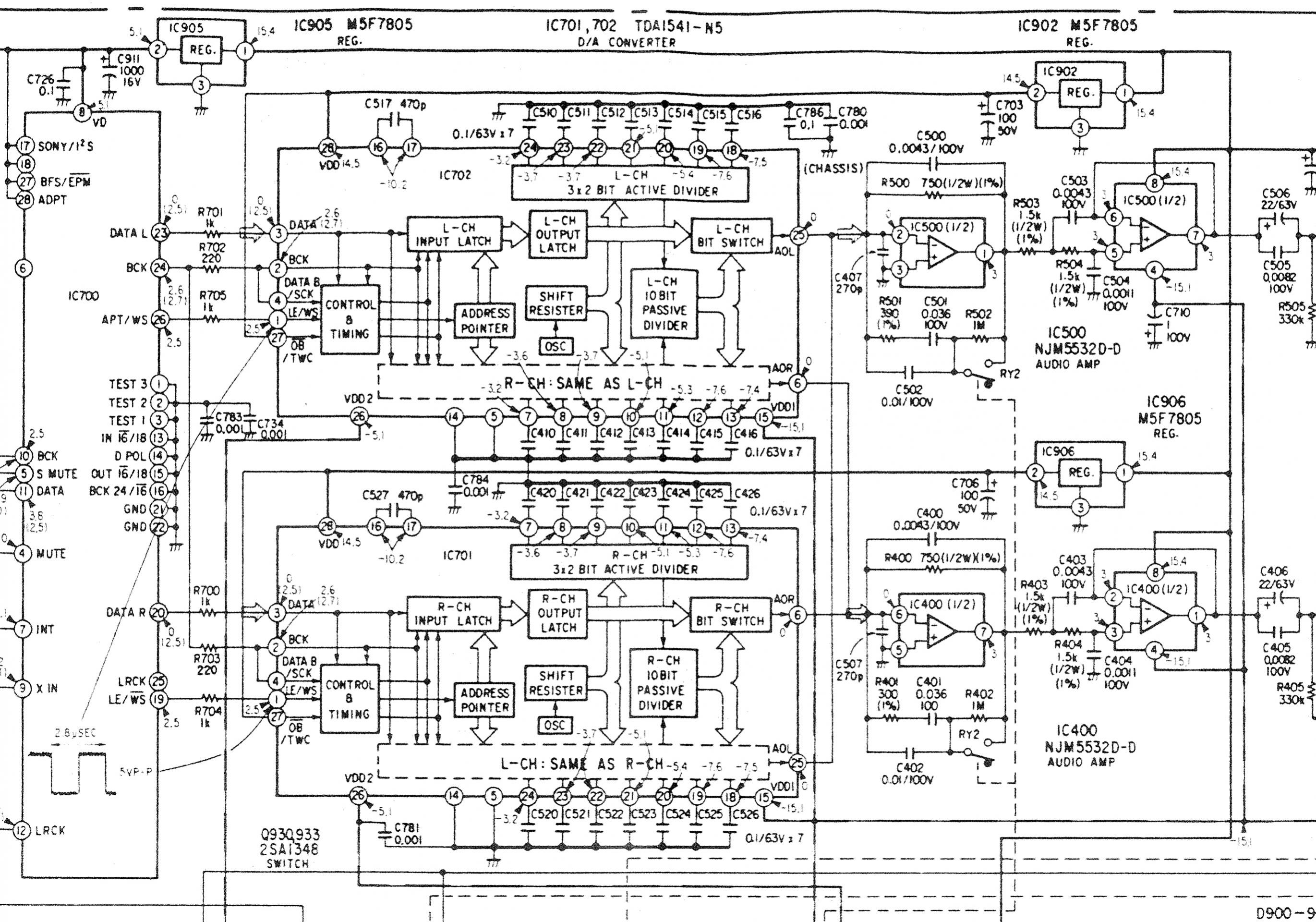
This is hpw Sony paralleled two TDA1541 in a Sony CDP-337.
On the left the digital Filter, on the right the output stages.
IC700: CXD1144P
IC400&500: NJM5532D
Curious, what the TDA1541-N5 means...
On the left the digital Filter, on the right the output stages.
IC700: CXD1144P
IC400&500: NJM5532D
Curious, what the TDA1541-N5 means...
Attachments
Last edited:
Curious, what the TDA1541-N5 means...
As an owner of a 337 I'm very curious about this too! I wonder if it is some sort of selection criteria?
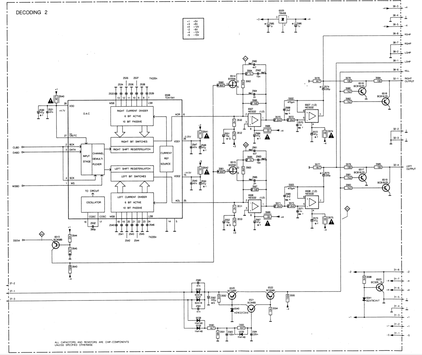
I would like to parallel two TDA1541 in a Philips CD304MKII.
But an 8V voltage is fed to the current output of the TDA1541,
see resistors in the attached drawing
3550 3552 and cap 2551 for the right channel
and resistors 3551 3553 and cap 2552 for the left channel.
+3 is misleading, for some strange reason Philips used symbol numbers
for voltages +3 in fact means +8V, a key table explaining the numbers is in the upper center of the schematics.
Very annoying when reading schematics...
Do I have to change the values of this voltage-injection when two TDA´s are parallelled?
Some thoughts why a voltage is injected into the Dacs current are here:
TDA1541-why is a Voltage fed into the Current Output?
Could have to do something with the fact that the TDA only puts out positive currents, but this voltage injection is not in every design.
Could this injection be part of the combination of SAA7220P/A together with TDA1541 non"A"?
The SAA1720P/A used in the CD304MKII player (with TDA1541 non A) produces a
"5% offset" whereas a SAA7220B/P priduced 0.05% offset, see this link:
Type Differences Philips SAA7220P/A, /B & /C
But I frankly do not understand what offset is meant and if there is a connection to the mentioned voltage injection...
I found schematics of this first generation SAA7220/TDA1541-non-A combination where no voltage/offset is inducted.
But those all use LM833 as Opamps and not the NE5534, where the injection can also be found.
On the other hand, the ones I found
All the best,
Salar
Last edited:
...ah, time for editing ran out!
...on the other hand, the paralleled TDA1541A in the Sony CDP-337 mentioned above uses the NE5532 as well. No injected voltage, but the digital filter is from Sony.
I assume the voltage injection in the Phillips CD-304MKII and CD960 is related to the combination of Filter (SAA7220, first version) TDA1541 (non A, first version) and Opamp NE5532?
- Status
- This old topic is closed. If you want to reopen this topic, contact a moderator using the "Report Post" button.
- Home
- Source & Line
- Digital Source
- Parallel TDA1541A DAC Noise