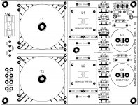
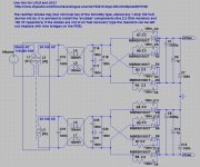
Finally got around to do some testing, and starting with the pre-reg boards i ran into a strange problem.
Ramped it up with a Variac, and one board is fine with +/- 41V and 4mA input current without load
The other board however started with about +/- 39V at 225V input, but then the + side started to slowly go up in voltage, and i gave up when it reached 48V. The no-load current was constant at 2 mA. The increase in voltage was about 10 - 20 mV per second at a constant input of 225V
Checked the soldering, but could not find any obvious fault. If somebody has a suspicion of what might be wrong, kindly let me know.
Thank you for your reply.
There are two boards, and each has two transformers - in case you are not familiar with the setup:


The reason i gave up at +48V is that the smoothing capacitor is (only) rated 50V.
Those are my thoughts:
There must be a reason the + side of one board behaves the way it does. The voltage can not increase like that just because it feels like it . My knowledge is sadly lacking to come up with an explanation, but since there are not many components i thought somebody knowledgeable could pinpoint my mistake easily
There are two boards, and each has two transformers - in case you are not familiar with the setup:


The reason i gave up at +48V is that the smoothing capacitor is (only) rated 50V.
Those are my thoughts:
There must be a reason the + side of one board behaves the way it does. The voltage can not increase like that just because it feels like it . My knowledge is sadly lacking to come up with an explanation, but since there are not many components i thought somebody knowledgeable could pinpoint my mistake easily
I do not have any 1W resistors in that range, but i think connecting the RC board instead would do equally well?I'm not sure the voltages you are reading are very meaningful without a load. Could you put some resistors across the outputs for a couple of minutes - say 470 ohms 1W and check the voltages?
Ok, reporting:
found a 300R 3W resistor, connected it to the V+ output.
Input voltage: 165 V (when i went higher, the resistor got too hot)
Input current: 14 mA
Output voltage into 300R: +20 V
Output voltage no load: -29 V
This would confirm that the output voltages without load are not particularly meaningful.
Voltages from the secondaries of the transformers at 165 V input
on the side loaded with 300 R: 17.5 V/17.6 V
side without load: 19.3V/19.4 V
That looked promising, so i did connect one board to one side of the RC-board.
The output from the + and - side was within 0.1 V and stable, and the second board showe3d similar values.
Ordered some 560R 3W resistors and will connect them to the RC-board and hook up both PSU boards. If that looks ok, the next step is to connect the regulator part of the main boards.
Gentlemen, thank you for your help
Fakeall, its worth running the back end of the board from a bench +/-18v supply before connecting the shunt regs. It let's you isolate faults in the input, riaa, & output stage from interactions between shunt reg and the rest of the board.
Though it does Seem like the mods on sebs boards, smt caps under the shunt and input rail caps have eliminated the problems some saw with original boards.
Though it does Seem like the mods on sebs boards, smt caps under the shunt and input rail caps have eliminated the problems some saw with original boards.
Just had a look at the OPA134 opamp, because i seem to have forgotten to order it, and wanted to check whether there was a substitute.
Reading the datasheet of the OPA134, the absolute max input voltage is specified as 36V (V+ to V-), and the Paradise schematic shows a direct connection to the 18V rails. Is that healthy, i wonder?
Will try NE5532 to start with, (Vmax 44V and slightly lower noise than the OPA134) unless there is a serious objection?
Thank you for your comments.
- Home
- Source & Line
- Analogue Source
- Paradise Builders