i just put the transistor in place and pushed the clips on (it takes quite much power to get them in place) This way there is no need for isolating jacket - just a isolation pad behind the transistors.
When i build my next paradise i'll probably order isolated transistors.
When i build my next paradise i'll probably order isolated transistors.
@RollE2k: I am not so strong as you, I failed doing it this way and I didnt want to use tools
If i remember right, i just checked that the transistor sat where i wanted, then put the clip on, and pushed the clip in place with a large square wood-piece or so. Makes it alot easier when you have something larger to push with.
If i remember right, i just checked that the transistor sat where i wanted, then put the clip on, and pushed the clip in place with a large square wood-piece or so. Makes it alot easier when you have something larger to push with.
used large pliers (the same that plumbers use) but other than that the same process
used large pliers (the same that plumbers use) but other than that the same process
Folks
A small G-clamp works perfect as well
")
take care Werner
Last edited:
Just bend the clips slightly open with thin nose pliers before fitting all the transistors, then you can fit the heat sink and the back pad to all 6 at once if you line them up carefully.
I'm not to sure that this is a good idea
Thank you all for the hints
I did the following: I have mounded the heatsink with the 3 screws to the PCB,
soldered all 6 devices with one lead at the proper position, added the isolation pads and used a "glue clamp" to fix the clips one by one, resoldered the 6 leads to minimize mechanical stress and finally soldered the rest of the leads.
I went well and I have no isolation problems.
(Checked with Multimeter)
I'm not to sure that this is a good idea
I've done it on all 9 units I've built, works every time. Of course I'm using one big pad and not six little ones.
Oké after firing up the pre-regultaor wich worked perfect,it was time to do the same to the phonostage......
And there was my first real problem.....
Al was going well,but than i had to measure the voltage of de gate/source of the pmos/nmos......
No 2,5v to find.....
What i'm measuring:
-gate 13v
-drain 0v
-source 18v
on both of the units
The output was a perfect 18v.....
An externally hosted image should be here but it was not working when we last tested it.
An externally hosted image should be here but it was not working when we last tested it.
An externally hosted image should be here but it was not working when we last tested it.
And there was my first real problem.....
Al was going well,but than i had to measure the voltage of de gate/source of the pmos/nmos......
No 2,5v to find.....
What i'm measuring:
-gate 13v
-drain 0v
-source 18v
on both of the units
The output was a perfect 18v.....
No 2,5v to find.....
What i'm measuring:
-gate 13v
-drain 0v
-source 18v
on both of the units
The output was a perfect 18v.....
Hi dre73, have you measured the voltages with a DMM with reference to GND? The sources of both MOSFETs (for the positive and negative shunt regulator) are connected to GND, so the voltage should be zero????
From the picture, it seems the long LED strings are not on, can you please check if you mounted the LEDs the right way?
PS: The 330Ohm vs 120Ohm is no concern right now.
Hi dre73, what exactly is the problem? I am lost.....
Did you connect the prereg to the phono stage? Do you measure +18V and -18V at the regulator output, and all LEDs shining`? Then it seems your regulators are OK.
Next step would be to solder the bridges to the amplifier and measure again. Please advise whats happening. By the way, this whole procedure is described in a lot of detail in the assembly guide
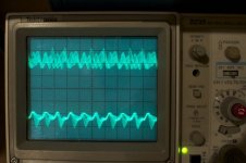
Boy am I slow… Finally got around to do this, on both boards, and they still oscillate. The photo below shows the oscillations, at 0.1 V per division.I populated my R3 boards a while back, with the 330 ohms. Will try to reduce them to 120 ohms and report back if this stops the oscillations... Thank you Alfred!
B.t.w. I am testing without any load. Am I correct in assuming these should be stable without load?
One one of the board, I have changed every transistor except the two MOSFETs.
Sorry to bother folks with this...
Attachments
- Home
- Source & Line
- Analogue Source
- Paradise Builders