...to continue andy...
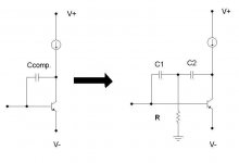
the figure below represents a typical transadmittance stage with first single-pole miller compensation, and then two-pole compensation.
..if the two are to give the same Wt, and hence identical maximum slew rate, then:
C1//C2=Ccomp.
where,
C2>C1
By the way, the location of the zero restoring single-pole roll-off is straightfowardly given by:
Fz=1/{2*pi*(C1//C2)R}
The two pole network reduces the current demands on the first stage below the zero by more than an order of magnitude compared to ordinary miller comp.
This causes a drastic reduction in so-called slew induced distortion for the same maximal slew....
....which indicates that you need not have a vast maximal slew in order to have low gm input stage nonlinearity in the audio band......
Attachments
...Therefore Andy...
........your summery is only valid for the single pole compensation, and then only if your compensation capacitor has to swing relatively large voltages.....say,...>>50V peak to peak.
......in which case i would probably settle for a MOSFET output stage with well controlled gain, incorporating the modifications i have outlined above.
")
........your summery is only valid for the single pole compensation, and then only if your compensation capacitor has to swing relatively large voltages.....say,...>>50V peak to peak.
......in which case i would probably settle for a MOSFET output stage with well controlled gain, incorporating the modifications i have outlined above.
Re: Re: a big enough liabilities
Transient response of current sources is extremely relevant and audible. The output impedance of the current source starts to drop above a few kHz. The current source on the front end differential pair contributes to the PSRR and CMRR of this stage.
Noise from the supply and common mode noise on the input extend into the RF range and the performance even at these frequencies is important. There is a bit more than DC involved despite any imagined assaults on your dignity.
Regulated power supplies are used to increase the effective PSRR by reducing the power supply noise seen by the circuit is supplying. The power supply for the amplifiers front end (that is every thing but the output stage) is often regulated. the sonic benefits of this are pretty well established. Regulators for the output stage are sometimes used but the current involved and the supply voltage overhead makes this expensive. There are even rumors that an audio circuits has a very great influence on the sound of amplifier. Probably started by someone outside the AES though and therefor highly suspect.
Zener filtering........ Let's see, 20 ohms and 1000uF gives a corner frequency of about 8 Hz. A 1000uF cap is fairly small and larger values could easily be used. A good 1000uF low ESR cap still has very good high frequency characteristics is why I picked it as an example. Audio tweakers have been bypassing zeners with large electrolytics for decades now. I guess they did know any better.
Source resistors do protect mosfets in the event of a short circuit. A power mosfet has a very low on resistance and the peak current into a short will toast the mosfet with no series resistor. Ask anyone who has owned a Counterpoint SA12 how reliable mosfets with no source resistors are. This is a no brainer, even for someone who is not a member of the AES.
I have no big objection to servos if they are designed well. Op amps have much better DC precision that simple diff pairs built with discrete transistors. If you are going to use a servo use a good one though.
I have read hundreds of articles in the AES and wireless world and some were very interesting. The problem is that many of the theories just aren't that useful in building good sounding amplifiers. How many distortion mechanisms have been discovered and fallen by the wayside. I remember all this slew rate hysteria the first time it was the big thing. Guess what? It's not. There are plenty of amps with fairly low slew rate numbers that sound very good. Just like the ultralow distortion and high bandwidth craze, this hasn't advanced audio amplifier design.
I learned much more about audio design from reading the Audio Amateur, High Fi News and Record Review, and application notes; than from the AES journal. Don't forget this is the same group that gave us an incredibly flawed balance digital audio data interface. I prefer to learn audio design from people who actually listen to the results instead of a bunch of PHDs from the academic community. I have no problem with some theory and math ( I do have a BSEE and actual engineering work experience in the real world) but I will never understand why some people are so scared to listen to amplifiers as part of the design process. Concentration a a pet theory is easier than doing the work building and modifying amplifiers to see what kinds of things actually make good sounding amplifiers. I got the silly idea somewhere that the whole point of audio design was to listen to the results in the end.
Again out of curiosity I ask, how many amplifiers have your actually designed, built, modified, or even repaired?
mikek said:
I generally do not take anybody who suggests they can 'hear' the 'sound' of an active DC current source...seriously.
The idea that the 'transient response' of the tail current source in a differential stage somehow affects the 'sound' of an amplifier is something i will not dignify with further comment.
True...regulated power supplies shouldn't be relied upon to improve PSRR......the gain stage can very easily be designed to have excellent PSRR without using such....but what has this got to do with output stages with gain in general?
Filtering power supply zeners is one of the great redherrings of all time...the dynamic impedance of a typical zener is of the order of 10~100 ohms....the capacitor size required to generate anywhere near a sufficiently large time constant to effect filtration across the audio band is trully heroic
No...you're unlikely to have thermal runaway with MOSFETS...negative temp.co. of drain current....or positive temp. co. of on-resistance...same thing.
And...No....source resistors do not help protect the output devices from S.O.A violation...they do however, prevent the matching of these device from getting excessively finicky in a multiple-parallelled complementarydevice output stage.
Good designs shouldn't need servos....
Considering that bias to the output devices is provided indirectly by the driver, and that infact these MOSFETS are undegenerated, and are unlikely to have their Vgs(th) matched to better than 2%, i find your lack ofconcern rather surprising.
This might not be as serious a problem, if the output stage and its driver were wrapped in a 100% series-voltage feedback loop, as this would tend to make bias stability less unstable.
...however this is not the case here......
Not having the intellectual aptitude to appreciate the work of those who take the time to contribute to JAES and other similar journals does not give you the right to denegrate or belittle their work.
To disagree with their findings is perfectly acceptable, and often welcome, but requires the presentation of rigorous and intellectually sound grounds.
I am satisfied from your presentation here that this is well beyond your abilities.
Transient response of current sources is extremely relevant and audible. The output impedance of the current source starts to drop above a few kHz. The current source on the front end differential pair contributes to the PSRR and CMRR of this stage.
Noise from the supply and common mode noise on the input extend into the RF range and the performance even at these frequencies is important. There is a bit more than DC involved despite any imagined assaults on your dignity.
Regulated power supplies are used to increase the effective PSRR by reducing the power supply noise seen by the circuit is supplying. The power supply for the amplifiers front end (that is every thing but the output stage) is often regulated. the sonic benefits of this are pretty well established. Regulators for the output stage are sometimes used but the current involved and the supply voltage overhead makes this expensive. There are even rumors that an audio circuits has a very great influence on the sound of amplifier. Probably started by someone outside the AES though and therefor highly suspect.
Zener filtering........ Let's see, 20 ohms and 1000uF gives a corner frequency of about 8 Hz. A 1000uF cap is fairly small and larger values could easily be used. A good 1000uF low ESR cap still has very good high frequency characteristics is why I picked it as an example. Audio tweakers have been bypassing zeners with large electrolytics for decades now. I guess they did know any better.
Source resistors do protect mosfets in the event of a short circuit. A power mosfet has a very low on resistance and the peak current into a short will toast the mosfet with no series resistor. Ask anyone who has owned a Counterpoint SA12 how reliable mosfets with no source resistors are. This is a no brainer, even for someone who is not a member of the AES.
I have no big objection to servos if they are designed well. Op amps have much better DC precision that simple diff pairs built with discrete transistors. If you are going to use a servo use a good one though.
I have read hundreds of articles in the AES and wireless world and some were very interesting. The problem is that many of the theories just aren't that useful in building good sounding amplifiers. How many distortion mechanisms have been discovered and fallen by the wayside. I remember all this slew rate hysteria the first time it was the big thing. Guess what? It's not. There are plenty of amps with fairly low slew rate numbers that sound very good. Just like the ultralow distortion and high bandwidth craze, this hasn't advanced audio amplifier design.
I learned much more about audio design from reading the Audio Amateur, High Fi News and Record Review, and application notes; than from the AES journal. Don't forget this is the same group that gave us an incredibly flawed balance digital audio data interface. I prefer to learn audio design from people who actually listen to the results instead of a bunch of PHDs from the academic community. I have no problem with some theory and math ( I do have a BSEE and actual engineering work experience in the real world) but I will never understand why some people are so scared to listen to amplifiers as part of the design process. Concentration a a pet theory is easier than doing the work building and modifying amplifiers to see what kinds of things actually make good sounding amplifiers. I got the silly idea somewhere that the whole point of audio design was to listen to the results in the end.
Again out of curiosity I ask, how many amplifiers have your actually designed, built, modified, or even repaired?
Hey Professor.....
Did you and I read the same book??? Isn't that what they said?
Somehow I think our disagreement is all a matter of semantics. We see the same thing and come to different conclusions.
For the record:
Phred has nothing to do with any of my responses.
I believe that the title you have chosen for this thread has caused great confusion.
DIY members asked my privately if I understood what the point was. Indeed, some did so early on in this thread.
Yes, you brought up many things that you have chosen to share. I'm sure many are grateful. I would not ever suggest that you should not do such.
I will suggest that perhaps next time you will think how the average DIY type might interpret the message you want to convey. It would be welcome by many.
Jocko
ahhhh yes...
....yet another output stage with gain greater than unity....
http://diyaudio.com/forums/showthread.php?s=&threadid=14061
...the designer missed the point somewhat i fear......the output stage can more elegantly be driven from the op amps. supply pins.....
........output stage bias is likely to be somewhat unstable.......
....and..what....no SOA protection....?
....'sides, insufficient BJT's for true 150W-8R, 300w-4R....
...Naahhh would give it a miss....
This thread is back again in SS Forum. I split the original part and moved off topic posts here http://www.diyaudio.com/forums/showthread.php?s=&threadid=14693
If you find a better title, let me know and I'll change it
Mikek, I would also appreciate that you try to keep this thread in order and please address Jocko and Fred with their proper names.
If you find a better title, let me know and I'll change it
Mikek, I would also appreciate that you try to keep this thread in order and please address Jocko and Fred with their proper names.
Re: Re: Re: a big enough liabilities
While I agree with this in principle, it's been my observation that to the vast majority of those who profess to only care about how things sound (the so-called "audiophiles") there's still a singular, underlying obsession with objective technical performance and a near 1:1 correlation between objective technical performance and "sounds good" or "sounds better."
It's as if no one can admit to something sounding good or sounding better than something else without also somehow linking it to some sort of improvement in objective technical performance.
Even the condemnation of the AES you give above about the AES/EBU interface is rooted in it being objectively, tehchically flawed. You might say "Yeah, but it also sounds like crap" but that just reinforces the correlation between objective techincal performance and good sound.
So why bother listening? If you can improve some objective technical aspect of performance, you're virtually guaranteed that it will sound better.
se
Fred Dieckmann said:I learned much more about audio design from reading the Audio Amateur, High Fi News and Record Review, and application notes; than from the AES journal. Don't forget this is the same group that gave us an incredibly flawed balance digital audio data interface. I prefer to learn audio design from people who actually listen to the results instead of a bunch of PHDs from the academic community. I have no problem with some theory and math ( I do have a BSEE and actual engineering work experience in the real world) but I will never understand why some people are so scared to listen to amplifiers as part of the design process. Concentration a a pet theory is easier than doing the work building and modifying amplifiers to see what kinds of things actually make good sounding amplifiers. I got the silly idea somewhere that the whole point of audio design was to listen to the results in the end.
While I agree with this in principle, it's been my observation that to the vast majority of those who profess to only care about how things sound (the so-called "audiophiles") there's still a singular, underlying obsession with objective technical performance and a near 1:1 correlation between objective technical performance and "sounds good" or "sounds better."
It's as if no one can admit to something sounding good or sounding better than something else without also somehow linking it to some sort of improvement in objective technical performance.
Even the condemnation of the AES you give above about the AES/EBU interface is rooted in it being objectively, tehchically flawed. You might say "Yeah, but it also sounds like crap" but that just reinforces the correlation between objective techincal performance and good sound.
So why bother listening? If you can improve some objective technical aspect of performance, you're virtually guaranteed that it will sound better.
se
Re: Re: Re: Re: a big enough liabilities
Amen!.....Yes lord!!!
Steve Eddy said:
While I agree with this in principle, it's been my observation that to the vast majority of those who profess to only care about how things sound (the so-called "audiophiles") there's still a singular, underlying obsession with objective technical performance and a near 1:1 correlation between objective technical performance and "sounds good" or "sounds better."
It's as if no one can admit to something sounding good or sounding better than something else without also somehow linking it to some sort of improvement in objective technical performance.
Even the condemnation of the AES you give above about the AES/EBU interface is rooted in it being objectively, tehchically flawed. You might say "Yeah, but it also sounds like crap" but that just reinforces the correlation between objective techincal performance and good sound.
So why bother listening? If you can improve some objective technical aspect of performance, you're virtually guaranteed that it will sound better.
se
Amen!.....Yes lord!!!
mikek said:
Filtering power supply zeners is one of the great redherrings of all time...the dynamic impedance of a typical zener is of the order of 10~100 ohms....the capacitor size required to generate anywhere near a sufficiently large time constant to effect filtration across the audio band is trully heroic
Fred dieckman said:
Zener filtering........ Let's see, 20 ohms and 1000uF gives a corner frequency of about 8 Hz. A 1000uF cap is fairly small and larger values could easily be used. A good 1000uF low ESR cap still has very good high frequency characteristics is why I picked it as an example. Audio tweakers have been bypassing zeners with large electrolytics for decades now. I guess they did know any better.
nyet....

Attachments
Re: Basic electronics
The idea that an appreciable reduction in DC resistance accrues by merely capacitively shunting the zener is illusory.
.....think Giga farads...
ALW said:Yeah great - we can use a smaller C by degrading the LF impedance of the reference dramatically. Not much cop as a DC reference now.
I guess this doesn't matter
The idea that an appreciable reduction in DC resistance accrues by merely capacitively shunting the zener is illusory.
.....think Giga farads...
I don't get it
I never said it was, but you've raised it by the value of R2.
think ohms law...
The idea that an appreciable reduction in DC resistance accrues by merely capacitively shunting the zener is illusory.
I never said it was, but you've raised it by the value of R2.
think ohms law...
Re: ....Interesting....
Why are you ZIPping up GIFs? I spent far more time firing up WinZip and unZIPping it than that 1% compression saved me in downloading it.
se
mikek said:........nother thought provoking example of an output stage with gain....complementary common-source, (from japan):
P.S: The driver bJT's, (2sc4793/2sa1837), are excellent!
Why are you ZIPping up GIFs? I spent far more time firing up WinZip and unZIPping it than that 1% compression saved me in downloading it.
se
ALW said:
I never said it was, but you've raised it by the value of R2.
think ohms law...
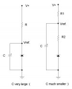
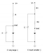
Ahhh...i see what you mean........ there is an error in the second figure...Vref. should be across the zener diode, and not the zener+R2...apologies for any inconvenience caused....
....However, C cannot be used to lower the DC output resistance of the reference.....
infact this can never be achieved by merely capacitively shunting the zener.....
...the idea is to improve the regulation of the voltage drop across the zener by diminishing power supply ripple in the current established by the resistors R, in the first figure, and R1, R2 in the second, where it can be assumed that R=(R1+R2)
Connecting C directly across the zener as in the first figure, is sub-optimal, as a commensurately larger component would then be required for the same time constant.
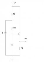
Should you feel an overwhelming compulsion to lower the zeners output resistance, then something along these lines is recommended:
Attachments
Re: Now you don't get it
Like for starting arguments on audio websites perhaps?
se
ALW said:Maybe the C is across the Zener for other reasons
Like for starting arguments on audio websites perhaps?
se
- Status
- This old topic is closed. If you want to reopen this topic, contact a moderator using the "Report Post" button.
- Home
- Amplifiers
- Solid State
- Output stages with gain Enhance Slew rate