Hi all,
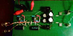
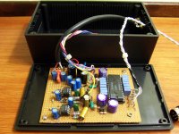
I built a new DAC output stage. It has sockets to fit different opamps. So with OPA604AP output stage works ok but with LM6181 and AD811 I listened a big bzzzzzzzzzzzz and they heat a lot.
Any comments or suggestions are very welcome (and sorry my English).
Katapum
I built a new DAC output stage. It has sockets to fit different opamps. So with OPA604AP output stage works ok but with LM6181 and AD811 I listened a big bzzzzzzzzzzzz and they heat a lot.
Any comments or suggestions are very welcome (and sorry my English).
Katapum
Attachments

circuit looks ok, but needs high speed prototyping, also the .1 uf may be too big, for >>10 MHz I'd use 10nF or even 1nF to keep srf freq high
maybe you could use a socket on a clearance-hole ground plane perf board but for best performance with really fast op amps "dead bug" technique works best
you need Linear Technology an47 "High Speed Amplifier Techniques" - its really big, long download time
search linear.com for: high speed amplifier techniques
"dead bug" proto technique - start with a bare copper clad pcb:
Attachments
The Saint said:
I would try a 10pf to 22pf cap across the Rf resistor.
...
that would be wrong with the decomp high speed amp and the current feedback amp, it would guarantee oscillation
passive i/v is going to be noisey, using ultra low noise op amps like AD797 or LT1028 would be better than the cheap LP record noise levels you'll get with the opa604
any dac i/v stage needs filtering, non-OS designs especially, sin(x)/x droop needs eq and images are bad because they generate imd that folds down into the audio band, the starting place here is paralleling the i/v resistor with a Cap, then follow up with 2nd order filter stages aligned to create a odd order filter with the correct frequency response
a Cap in parallel with the i/v R also soaks up dac glitch energy that could generate distortion in th op amp input - esp if you go to bipolar input for lower noise
Hi,
I echo previous poster, add a 10nF ceramic directly across pin4 to pin7.
On a slightly different tack.
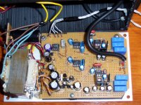
What voltage have you got before the regs?
32Vac secondaries are very high for 7815 & 7915.
A split 2*16Vac would be OK.
What is it feeding? The 470nF output cap will become a bit small into low impedance loads.
I echo previous poster, add a 10nF ceramic directly across pin4 to pin7.
On a slightly different tack.
What voltage have you got before the regs?
32Vac secondaries are very high for 7815 & 7915.
A split 2*16Vac would be OK.
What is it feeding? The 470nF output cap will become a bit small into low impedance loads.
Hi,
Before i wrote post #1 i tried it with a 100nF MKT and didn´t work.
i only have a 2x32Vac transformer (no centred tap).
What’s the “best” opamp to my dac output stage?
(I only have in my place: OPA604, LM6181, AD811).
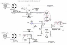
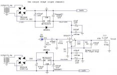
So the new schematic will be:
Is it ok?
Katapum
I echo previous poster, add a 10nF ceramic directly across pin4 to pin7.
Before i wrote post #1 i tried it with a 100nF MKT and didn´t work.
32Vac secondaries are very high for 7815 & 7915. A split 2*16Vac would be OK.
i only have a 2x32Vac transformer (no centred tap).
passive i/v is going to be noisey, using ultra low noise op amps like AD797 or LT1028 would be better than the cheap LP record noise levels you'll get with the opa604
What’s the “best” opamp to my dac output stage?
(I only have in my place: OPA604, LM6181, AD811).
So the new schematic will be:
Is it ok?
Katapum
Attachments
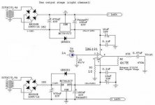
Katapum, you are comparing voltage-feedback op-amps with current-feedback op-amps, and exchanging them on the same circuit. They are totally different.
I would use a series input resistor (820R would do), BUT you are using 820R for feedback on the LM6181, with a 52.25x gain, and National recommends lowering that resistor to 500R for higher gains (~25x and up).
Also, some op-amps don't really like high dc-offset on their inputs.
I would use a series input resistor (820R would do), BUT you are using 820R for feedback on the LM6181, with a 52.25x gain, and National recommends lowering that resistor to 500R for higher gains (~25x and up).
Also, some op-amps don't really like high dc-offset on their inputs.
Hi,
I am getting side tracked, but it looks like you have 31Vdc on the filter caps from 32Vac secondaries. This does not add up. It should be near 45Vdc.
If the voltage is too high on the regs they will probably fail.
Try wiring the primaries of the two transformers (both need to be the same) in series to effectively half the output voltage seen on the first cap. 20Vdc is enough to give 15Vdc post regulator.
Hi,
See attached file. I tried it and….nothing again….the same stupid noise. I tried with and without 820R input resistor.
Katapum
I would use a series input resistor (820R would do), BUT you are using 820R for feedback on the LM6181, with a 52.25x gain, and National recommends lowering that resistor to 500R for higher gains (~25x and up).
See attached file. I tried it and….nothing again….the same stupid noise. I tried with and without 820R input resistor.
Katapum
Attachments
Katapum said:Hi,
See attached file. I tried it and….nothing again….the same stupid noise. I tried with and without 820R input resistor.
Katapum
In place of that, try a coupling cap, and then a resistor to ground. This is between the 15R I/V resistor and NI input of the op-amp.
Not the ideal solution, but if it works and you insist on using these op-amps...
How did you listen to the noise? Headphone directly at the OP Amp output? Or with speakers?
IMO, as JCX stated already, it woud be a good thing to bandwith limit the input of the OP Amp with at least a first order filter putting a cap in parallel to the I/V resistor. The DAC output produces very steep transients, and you are going to pass that through all following gear, especially with those fast OP Amps.
Btw, I would ask the Moderators to move this thread to "Digital". The title suggests a power amp problem......
In the digital forum, I believe there are some more people with experience in passive I/V and an OP AMP after that.
Success, Tino
zinsula said:In the digital forum, I believe there are some more people with experience in passive I/V and an OP AMP after that.
Me.

Btw I use a 200pF styroflex cap after the I/V resistor.
Yes, that can be the cause of Katapum having noise with very fast, high bandwidth op-amps.
Attachments
Hi,
What’s the ideal solution?
My dac schematic: (http://users.podolsk.ru/boga/DAC.html). I also built a sin x/x correction circuit.
Katapum
I tried with 0.1uF and 470k and finally I listened some music but with some noise.In place of that, try a coupling cap, and then a resistor to ground.
Not the ideal solution,
What’s the ideal solution?
My dac schematic: (http://users.podolsk.ru/boga/DAC.html). I also built a sin x/x correction circuit.
Tu? Preciso de provas!!!
Katapum
Katapum said:I tried with 0.1uF and 470k and finally I listened some music but with some noise.
Nice.
You don't have DC on the input of the op-amp now. Measure dc on the output and consider removing that cap.
But you will probably have some DC on the output with those current-feedback op-amps, so if you stick with them let it be. With a fet-input op-amp like the OPA627 you would only need the input coupling cap, but even that would not be mandatory.
Katapum said:Tu? Preciso de provas!!!
Why did you hear less noise now that you inserted the coupling cap? Because besides being used as a high pass filter (dc coupling), the cap also has a limited bandwidth, so it is also a low pass filter. As you used a small film cap, it doesn't do much in this respect. In any case, even if you used a (good) bipolar electrolythic, you still need a small cap after the I/V resistor to ground.
What's happening is that those very fast, high bandwidth op-amps are amplifying a lot of noise from the dac's output, and obviously the harmonics easily come down to the audioband.
I also use a small cap across the feedback resistor on the op-amp, but I can't advise you to use it with current feedback op-amps.
This one is active I/V (LM6171) , output stage is OPA627 + BUF634.
Attachments
Katapum said:Hi,
To Carlosfm:
What´s op amps have you in your TDA1541 output stage dac?
Katapum
OPA637, biased to class-A at ~8 ma.

- Status
- This old topic is closed. If you want to reopen this topic, contact a moderator using the "Report Post" button.
- Home
- Amplifiers
- Solid State
- Output stage instability