Hi all,
I had some spare time so i made more mods in my little circuit.
I made several mixes. I fitted different kinds of ampop in left and right channel and the results are:
Opa604 and opa604 circuit worked.
Opa604 and LM6181 circuit worked.
Opa604 and AD811 circuit worked.
AD811 and LM6181 circuit not worked I listed only noise.
AD811 and AD811 circuit not worked I listed only noise.
What could I try more?
PS: I burned one lm6181.
Katapum
Attachments
Katapum said:PS: I burned one lm6181.
Katapum
Wait a minute...

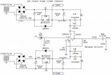
Are you sure you have (+/-) 15V after those 7815/7915 regs?
32V trafos? What for?

Btw (off-topic) that 321R series resistor on the output is waaaay too high. If you can have low output impedance, why don't you?
Hi,
Yes it´s an input resistor PSU.
No money for more…they hard times.
I agreed with you. I increased the value to get some sound.
Now I found the problem (I changed interconnects cables). BTW did you saw all fet line design by KYW (300R).
Katapum
Are you sure you have (+/-) 15V after those 7815/7915 regs?
Yes it´s an input resistor PSU.
32V trafos? What for?
No money for more…they hard times.
Btw (off-topic) that 321R series resistor on the output is waaaay too high. If you can have low output impedance, why don't you?
I agreed with you. I increased the value to get some sound.
Now I found the problem (I changed interconnects cables). BTW did you saw all fet line design by KYW (300R).
Katapum
Hi,
I burned a LM6181 because I inserted a parallel cap with feedback resistor.
I hear you but:
Now the stage is working. Its sounds better then my previous jfet stage. I didn´t like opa604 they are a little unreal. AD811 has an impressive micro detail but the mid band is a little aggressive.
I wiil buy one LM6181 and ….. two OPA134??? and maybe two opa637 (they very expensive)???.
More options please?
Katapum
I burned a LM6181 because I inserted a parallel cap with feedback resistor.
I raised the voltage problem way back but our thread starter does not hear!
I hear you but:
Maybe later.No money for more…they hard times.
Now the stage is working. Its sounds better then my previous jfet stage. I didn´t like opa604 they are a little unreal. AD811 has an impressive micro detail but the mid band is a little aggressive.
I wiil buy one LM6181 and ….. two OPA134??? and maybe two opa637 (they very expensive)???.
More options please?
Katapum
No money for more…they hard times.
You don't need more, you need less voltage
")
In case of overvoltage, Lxxxx regulators will probably malfunction, and so the op-amps.
Katapum, if you check the 78xx datasheet from National, the absolute max. input voltage these regulators can take is 35V (ex: LM7815).
With 32V trafos your DC voltage will be around 44V.
It doesn't smell good that you say you have 31V after the 3.3 ohm series resistors, after the rectifier diodes, as printed on your schematic. (?)
Another thing, just 470uF capacitance before the regs?
With 32V trafos your DC voltage will be around 44V.
It doesn't smell good that you say you have 31V after the 3.3 ohm series resistors, after the rectifier diodes, as printed on your schematic. (?)
Another thing, just 470uF capacitance before the regs?
Hi Katapum,
run just one secondary winding through the bridge rectifier to create your 45Vdc to 50Vdc supply.
Now create a false ground using a splitter made from caps and resistors or even an active ground using an opamp. Lots of circuits to do this.
Then you will have +-22Vdc to run into the two + & - regulators.
You are throwing resources at the wrong end of the circuit.
Sort the PSU before you waste even more money on toasted opamps.
Hi,
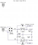
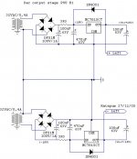
B1 is totally wrong throw it away quickly.
A1 is almost there.
Add balancing resistors after the rectifier.
1k0//470uF and 1k0//470uF. These resistors will run pretty warm so 1W or 2W might be better.
I think you should remove or reduce 3r3 series resistors before the caps.
I also think you should add a lot a capacitance to the PSU. eg. ceramic and PP or PES across the electros, spike suppression across the psu outputs and the rectifier AC and across the transformer mains side and before and after the regs.
Like I said earlier, invest some resources in the PSU BEFORE wasting money on expensive opamps. The PSRR of the opamps helps reduce all the HF hash coming from the mains and rectifier diodes but you should not be relying on that alone.
Have you fitted spike suppression cap across the opamp supply pins?
Hi,
Yes a 100nF stacked.
I found in a junk box:
One 12V-0-12V/1A transformer
2x 1000uF/35V
2x 18R/0.6W
2x 2200uF/35V
several 0.1uF/63V MKT
1x 7812
1x 7912
Katapum
Have you fitted spike suppression cap across the opamp supply pins?
Yes a 100nF stacked.
I found in a junk box:
One 12V-0-12V/1A transformer
2x 1000uF/35V
2x 18R/0.6W
2x 2200uF/35V
several 0.1uF/63V MKT
1x 7812
1x 7912
Katapum
- Status
- This old topic is closed. If you want to reopen this topic, contact a moderator using the "Report Post" button.
- Home
- Amplifiers
- Solid State
- Output stage instability