Hello Folks,
reviving this old thread, being inspired by the low RdsON and current capability of available Power-MOSFETs (threads about ideal rectifiers mention several alternatives...), because I feel uneasy about reliability of electromechanical Output-Relay contacts from experience.
So, what's the latest about using SS-relay at Speaker-Outputs?
Why would these be an alternative or why not?
I did not find threads about use of SS-relays substituting relay contacts other than this one, so I'm courious about why this is the case and am interested in potentially implementing SS-relays at the power outputs of my active speaker amps.
Greetings,
Winfried
Hi Winfried,
Please see the post by xrk971 here:
https://www.diyaudio.com/forums/gro...eaker-protection-delay-gb-11.html#post5875582
Very good results with SS relays.
I have also got extensive positive experience with SS relay-based protection systems, so if you have more questions - please let me know
")
Cheers,
Valery
Hello Valery,
thank you for the linked information! So, using SSR looks very promising!
In my 4-way active speaker the DC detection & protection as well as turn-on-delay circuit already exists and suits the needs well. It just uses relay contacts in the chassis lines, which I aim to replace by an SSR.
So, in essence, the complete RTR SSR is a great device, but has redundant functionality for my case. Adaptation of the existing protection circuitry to the optocoupler and MOSFETs as SSR looks relatively straight forward.
Thanks a lot! I did not anticipate it would be that "simple"

Regards,
Winfried
thank you for the linked information! So, using SSR looks very promising!
In my 4-way active speaker the DC detection & protection as well as turn-on-delay circuit already exists and suits the needs well. It just uses relay contacts in the chassis lines, which I aim to replace by an SSR.
So, in essence, the complete RTR SSR is a great device, but has redundant functionality for my case. Adaptation of the existing protection circuitry to the optocoupler and MOSFETs as SSR looks relatively straight forward.
Thanks a lot! I did not anticipate it would be that "simple"
Regards,
Winfried
Last edited:
Hello again!
Maybe some additional help can be provided to my SSR Quad Output Relay project...
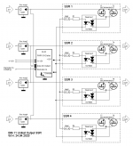
My project is small, i.e. because I only want to equip two 4-Way Speakers doing a lay-out with SMD seems like an overkill. Here's the schematic:

As you can see, sensing DC is directly done on the Amp Board and the "Unmute" output signals are generated by the protection board (ELSI - works already) to one SSR board per Amp.
My questions:
Does my Open Collector Transistor (which switched the output relay so far) circuit work or did I miss anything?
How can I solder/connect the TLP3906 and the BSC040N10NS10 without having an SMD board?
I'd be grateful for recommendations!
Regards,
Winfried
Maybe some additional help can be provided to my SSR Quad Output Relay project...
My project is small, i.e. because I only want to equip two 4-Way Speakers doing a lay-out with SMD seems like an overkill
. Here's the schematic:As you can see, sensing DC is directly done on the Amp Board and the "Unmute" output signals are generated by the protection board (ELSI - works already) to one SSR board per Amp.
My questions:
Does my Open Collector Transistor (which switched the output relay so far) circuit work or did I miss anything?
How can I solder/connect the TLP3906 and the BSC040N10NS10 without having an SMD board?
I'd be grateful for recommendations!
Regards,
Winfried
Attachments

Member
Joined 2009
Paid Member
So, in essence, the complete RTR SSR is a great device, but has redundant functionality for my case. Adaptation of the existing protection circuitry to the optocoupler and MOSFETs as SSR looks relatively straight forward.
Am glad that you have defined your requirement so clearly. I've been there too, though I've never designed anything around it. I don't know any better introduction to the issue than this page by Andrew Russell: Solid State Relay with PCB Layout The author is "bonsai" on these forums.
You guys really should take a look at my posted circuit. I'm using the Si8752 FET driver, it's NOT PhotoVoltaic based, it uses an internal RF generator/reciever that is capacitively coupled. (Data sheet) https://www.silabs.com/documents/public/data-sheets/Si8751-2.pdf [/URL] It provides greater drive current for quicker switching speeds than any PhotoVoltaic type, and it's rated for use with high current applications such as mains switching. There's also the Si8751 version which is digitally controlled.
Rod Elliott posted an article on his site about it here: Project 198
Mike
Rod Elliott posted an article on his site about it here: Project 198
Mike
Last edited:
Sounds nice, but looks like SMT only, no through hole option, unless I missed something.
Not for all DIYers.
Here's what I use: DIP-ADAPTER-EVM Texas Instruments | Prototyping, Fabrication Products | DigiKey
Makes it pretty easy.
There are 26 of these in my current (years-long) project. I'm not sure if I'll use the adapter boards or not, I don't find these all that difficult to work with in spite of my declining motor skills due to aging.
Mike
Last edited:
Makes it pretty easy.
If you're in a condition allowing you to handle it.
I don't find these all that difficult to work with in spite of my declining motor skills due to aging.
We're not all in the same condition and age. I surely couldn't handle this, any more. Many years ago, sure, but not happening nowadays. So through hole is the usable option.
Thanks a lot for the link! This really helps me!Am glad that you have defined your requirement so clearly. I've been there too, though I've never designed anything around it. I don't know any better introduction to the issue than this page by Andrew Russell: Solid State Relay with PCB Layout The author is "bonsai" on these forums.
Regards,
Winfried
Hi again!
Actually, I have a non technical question:
Has anyone done comparative listening Tests between conventional Relay and SSR?? What are the subjective results?
Please post your experience, a discussion on theoretical grounds would not help...
Thanks,
Winfried
My opinion...what I heard...no difference between having the speaker signal through the MOSFETs, and when I directly shorted the MOSFET's drains together by placing a good quality aligator jumper across the drain tabs of the MOSFETs, effectively by-passing them. I tried it with no signal, and at various power levels from low to high, and heard no difference, or added noises, clicks, or distortions of any kind. With the super-low Rds MOSFETs available today, one basically does have a straight through circuit either way.
Mike
We want the MOSFETs in a SSR to be low on Rds-on and high on BVds and (BVds/Rdson)^2 = $$$ + L*W*H, roughly speaking. So we often end up with marginal BVds de-rating, thus making it necessary to take measures to protect the MOSFETs.
Under extreme conditions when the SSR switches off an inductive load, as is the case a speaker, the back EMF kick can subject the MOSFETs to high Vds, possibly endanger them. A pair of clamping diodes at the output of the SSR, as shown in Michael Bean's post #664, would dump extra energy from the the kick to power supply rails, and the MOSFETs would not see a voltage greater than what's between the rails.
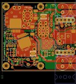
The attached layout is my implementation of a SSR speaker relay with a 200W amp project, Meistersinger, finished a few years ago, the D16 and D17 are the clamping diodes. I used 150V Vds rating MOSFETs against the +/-65V supply rails.
For add-on SSR projects, on the other hand, it's probably not favored to have to wire the supply rails to the SSR board for just clamping. A bi-directional TVS device could then be used across the SSR to make sure the MOSFETs don't see a voltage greater than the TVS's V_ break-down. Member XRK971's SSR group-buy project displays such practice. The TVS, at break down, would dump the extra back EMF kick energy to the output stage of the amp and then to the supply rails eventually.
Just a thought.
Under extreme conditions when the SSR switches off an inductive load, as is the case a speaker, the back EMF kick can subject the MOSFETs to high Vds, possibly endanger them. A pair of clamping diodes at the output of the SSR, as shown in Michael Bean's post #664, would dump extra energy from the the kick to power supply rails, and the MOSFETs would not see a voltage greater than what's between the rails.
The attached layout is my implementation of a SSR speaker relay with a 200W amp project, Meistersinger, finished a few years ago, the D16 and D17 are the clamping diodes. I used 150V Vds rating MOSFETs against the +/-65V supply rails.
For add-on SSR projects, on the other hand, it's probably not favored to have to wire the supply rails to the SSR board for just clamping. A bi-directional TVS device could then be used across the SSR to make sure the MOSFETs don't see a voltage greater than the TVS's V_ break-down. Member XRK971's SSR group-buy project displays such practice. The TVS, at break down, would dump the extra back EMF kick energy to the output stage of the amp and then to the supply rails eventually.
Just a thought.
Attachments
Hi again!
Actually, I have a non technical question:
Has anyone done comparative listening Tests between conventional Relay and SSR?? What are the subjective results?
Please post your experience, a discussion on theoretical grounds would not help...
Thanks,
Winfried
I only use SSR on my DIY stuff and my commercial amps.
I used a conventional relay on the Ovation 250 (which prompted this thread !) - that design dates back to 2005/2006.
SSR’s have no impact on the sound of you use the correct low Rdson devices. On my 240W commercial amp the distortion is below 7 ppm at 200 Watts into 8 ohms and most of that is due to the test measurement fear limits. Sims of the SSR show it’s at the parts per billion level at high power.
I should publicly thank Michael Bean here for bringing this approach to the table BTW! One of the better, more practical ideas to come to the forum over the last few years.
Last edited:
There is one practical comparison that I'd like to see for SSRs, perhaps put into a simple table for quick and easy viewing and understanding.
That is a comparison of inserting the SSRs into the ground return from the speakers as opposed to the hot side from the amp. I'm very tempted to use the grounded side, but could someone bring this to light for us?
Bonsai, I'm sure you've already gone through that comparison, so it would only be a matter of making up a quick table of pros and cons for both arrangements.
Plus there is one more thing I've been puzzling about: how to handle bridged amps. With both sides of the speaker output being "hot" from amps outputs, and no ground return. Obviously the main question is: do we really need to put SSRs on each side? I would assume it would be best to do so. But I'm curious to see what others have to say about that.
I switch the speaker ground on the nx-Amplifier protection board
BUT
If you short the speaker directly to the chassis, the SSR is bypassed so you have no protection in that eventuality.
On Bridged amps you only need 1 SSR but you have to take protection inputs from both amps so that if either fails, the SSR is activated.
BUT
If you short the speaker directly to the chassis, the SSR is bypassed so you have no protection in that eventuality.
On Bridged amps you only need 1 SSR but you have to take protection inputs from both amps so that if either fails, the SSR is activated.
Last edited:
Hi Mike,My opinion...what I heard...no difference between having the speaker signal through the MOSFETs...
interesting observations! So I Start asking myself: What would be the sound advantage of SSR over relay contacts? What’s the difference? Sorry, I did not read the whole thread...
Greetings,
Winfried
Last edited:
- Home
- Amplifiers
- Solid State
- Output Relays