Hi,
i found a suitable relay, which can be good for DC protetion:
Fujitsu FTR-J2 Series General Purpose Relays | Mouser
Sajti
i found a suitable relay, which can be good for DC protetion:
Fujitsu FTR-J2 Series General Purpose Relays | Mouser
Sajti
It's OK for current, but not able to cut the DC in case of the failure of any output device.
Sajti
Nor will your relay.
Use a crowbar ahead of the relay (to protect the relay), the relay just makes it quiet during turn-on and turn-off.
During a DC fault, when you attempt to open relay contacts the voltage will try to rise to infinity, and arc across the contacts. Even if you put magnets next to the contacts (like some Omron relays have). Sometimes caps across the relay can help (like points in an automobile).
"The Diodes across the speaker output to supply rails limits the voltage rise to Vf+Vsupply across the relay contacts. "
It's the back EMF from the speaker, and it slags the relay contacts. Welded solid. And if an output is shorted, the diode in parallel with it doesn't do much, does it (especially since the arc has already jumped back across the contacts)?
It's the back EMF from the speaker, and it slags the relay contacts. Welded solid. And if an output is shorted, the diode in parallel with it doesn't do much, does it (especially since the arc has already jumped back across the contacts)?
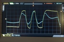
This is a 100W (+-50Vcd PSU) amplifier in normal operation. The blue trace is from the current probe and measures 10A/div (the maximum current shown is about 22A). Braking even normal operation, with an relay, is difficult under stress it will be even more difficult.
Attachments
The back EMF from the speaker is clamped to +/-(Vf+Vsupply) by the diodes. The EMF from the speaker only produces a voltage which rises toward infinity if there is no low impedance path for the current to go. The diodes provide a path for current to flow when the voltage at the output exceeds the rail voltages by Vf. A shorted output also provides a path for current to flow preventing infinite voltage. Worst case scenario is 2*Vsupply+Vf across the relay at short circuit current. E.g. the output is pulling down to -Vsup and the speaker EMF is pulling up to +Vsup+Vf so you have 2*Vsup+Vf across the relay contacts."The Diodes across the speaker output to supply rails limits the voltage rise to Vf+Vsupply across the relay contacts. "
It's the back EMF from the speaker, and it slags the relay contacts. Welded solid. And if an output is shorted, the diode in parallel with it doesn't do much, does it (especially since the arc has already jumped back across the contacts)?
Last edited:
"The back EMF from the speaker is clamped to +/-(Vf+Vsupply) by the diodes"
After the relay starts to open?
The diodes are not on the speaker side at that point.
I've seen 10A speaker relays smoke just driving a resistive load with a non-clipped, no DC signal.
"Braking even normal operation, with an relay, is difficult under stress it will be even more difficult. "
You got that right!
Why not? That's where I place mine."The back EMF from the speaker is clamped to +/-(Vf+Vsupply) by the diodes"
After the relay starts to open?
The diodes are not on the speaker side at that point.
"The back EMF from the speaker is clamped to +/-(Vf+Vsupply) by the diodes"
After the relay starts to open?
!
Yes, if they are connected on that speaker side of the relay.
Sajti
I've seen 10A speaker relays smoke just driving a resistive load with a non-clipped, no DC signal.
Yes, because most of the relays are not able to operate on high voltage DC. The parameters are confusing:
The Omron G2RL2 has the following parameters:
Maximum switchable voltage:300VDC
Maximum switchable current:16A
Sure, but not same time. It can interrupt 16A on maximum 30VDC, and it can interrupt 300VDC, but the current is only few mA in that case.
The relay, I mentioned, can break 10A AND 450V. It must be suitable in a common few hundred watts amplifier.
Sajti
What is the load during this measurement?This is a 100W (+-50Vcd PSU) amplifier in normal operation. The blue trace is from the current probe and measures 10A/div (the maximum current shown is about 22A). Braking even normal operation, with an relay, is difficult under stress it will be even more difficult.
100W into 8r0, or 8ohms(with some L&C), or 4r0, or 4ohms(with some L&C)?
then place them where they are needed. I use two sets of diodes on my amplifiers, they only cost 1.6p each when bought by the hundred."The back EMF from the speaker is clamped to +/-(Vf+Vsupply) by the diodes"...................
The diodes are not on the speaker side at that point.
and/or adopt a solid state relay.I've seen 10A speaker relays smoke just driving a resistive load with a non-clipped, no DC signal.
"Braking even normal operation, with an relay, is difficult under stress it will be even more difficult. "
You got that right!
What is the load during this measurement?
100W into 8r0, or 8ohms(with some L&C), or 4r0, or 4ohms(with some L&C)?
The load is a 8-ohm (nominal) loudspeaker system. Carver Amazing Platinum Edition. This is an magneto stat (2 pcs 70cm(28") line sources) with 4 cone (25cm(10") diameter) woofers in a panel.
You tested via a real speaker.
Pass the instantaneous peak current info on to the Cordell book Thread.
Some in there will not believe that peak current can ever exceed Vpk / (lowest real resistance of the speaker)
i.e. they insist that if a real 8ohms speaker has a resistance of 6r, then the peak current can never be more than Vpk/6
...i.e. they insist that if a real 8ohms speaker has a resistance of 6r, then the peak current can never be more than Vpk/6
Just my point.
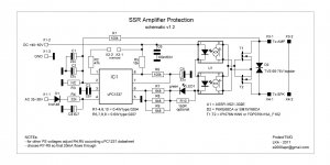
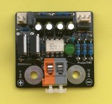
Hello, this is my first try to build a protection circuit by using solid state relay. I'm satisfied almost with all parameters but ON switch time is too slow due to LED circuit. If one does not plan to switch ON under heavy load everthing is superb. Question is, how to SPEED UP the circuit
- usable for 100-200W@4R amplifiers (one module per channel)
- resistance slightly less then 20 mOhm
- SSR ON time aprox 15 ms
- SSR OFF time aprox 5 us
- delay between overload detection and SSR OFF aprox 380us
See measurements
https://goo.gl/photos/3vb1LmGzPsKVRdWw9
- usable for 100-200W@4R amplifiers (one module per channel)
- resistance slightly less then 20 mOhm
- SSR ON time aprox 15 ms
- SSR OFF time aprox 5 us
- delay between overload detection and SSR OFF aprox 380us
See measurements
https://goo.gl/photos/3vb1LmGzPsKVRdWw9
Attachments
Looks good 
A quick thought on the photovoltaic couplers... have you considered running them in series (the outputs) to double the drive voltage available. I haven't looked at the FET specs, but may are rated up to 20Vgs or higher and so can benefit from being run in that region (lower Rds at higher Vgs).
Nice work though")
A quick thought on the photovoltaic couplers... have you considered running them in series (the outputs) to double the drive voltage available. I haven't looked at the FET specs, but may are rated up to 20Vgs or higher and so can benefit from being run in that region (lower Rds at higher Vgs).
Nice work though
- Home
- Amplifiers
- Solid State
- Output Relays