amplifierguru said:There are many simple protections available, that are cheap including fusible resistors which can replace individual Re on the outputs and 'PTC fuses or polyswitches' that can be put inside the feedback loop.
Not good...which is why most Sony amps. are to be avoided at all costs!
Not good...which is why most Sony amps. are to be avoided at all costs!
Applies to their recievers too. At least that makes sense of an unfortunate experience a few years ago.

mikeks said:
Not good...which is why most Sony amps. are to be avoided at all costs!amplifierguru said:There are many simple protections available, that are cheap including fusible resistors which can replace individual Re on the outputs and 'PTC fuses or polyswitches' that can be put inside the feedback loop.
sam9 said:Applies to their recievers too. At least that makes sense of an unfortunate experience a few years ago.
FWIW to both of you, I have never seen a fusable emitter resistor or PTC fuse in a Sony amp or receiver. The output protection that I have seen is output current monitoring via the emitter resistors, as well as DC detection. Can you point me to any specific recent model using the aforementioned cheap protection methods?
Hi macboy,
I've never seen these in Sony home product either (don't know about lifestyle). I do now they were used as tweeter protectors in speakers. The resistance does not reset to the same low starting value.
The breakers used in NAD receivers are the thing I'd warn people away from. Many I see are intermittent.
-Chris
Most receivers made in Japan that I have seen (70s~80s
) had fuseable (flameproof) base resistors on the outputs, between the emitters of the driver transistors, and on the emitters of the output transistors.
NAD used PTCs on the high voltage tiers of their power envelope series of amps and receivers.
) had fuseable (flameproof) base resistors on the outputs, between the emitters of the driver transistors, and on the emitters of the output transistors.
NAD used PTCs on the high voltage tiers of their power envelope series of amps and receivers.
mikeks said:
Vital...
The choice of SOA protection locus may also need to accomodate the choice of heatsink...viz: derate locus to roughly march tolerable dissipation with selected heatsink for indefinite shorts...AKA prolonged SOA violation...

But, Mike, you wouldn't design the SOA protection against prolonged shorts, would you? That would get out of hand quickly. What's your goal, 10 secs, 1 minute, 10 minutes? SOA protection should protect against momentarily excursions outside of the output devices allowed SOA to prevent them to break down, which would be an illegal combination of Vce and Ic. I know there is also a time factor involved, but it is "momentarily" like under a sec. for sure.
Prolonged shorts within the SOA should be taken care of by a thermal switch, you can't design the heatsinks for EVERY possible contingency.
Jan Didden
sam9 said:
A well designed VI limiter should be able to do all that AND not effect sound quality. I believe there are some that do all this. I also have experience with some that don't. And as you say some that are OK for a while until thermal failure enters.[snip]
Sam,
I don't think you can design a protection system that doesn't effect sound quality when it is activated. When activated, it modifies the amp's output and therefore necessarily impacts (negatively) sound quality.
If you mean that it should be transparent when not activated, yesI fully agree.
Jan Didden
Isn't 'slope protection' just a fancy word for current limiting?
The problem with current limiting is that if you have a partial short in a speaker terminal, wires or driver, you may not notice it, in other ways that your amplifier and the hot spot run incredibly hot. Or if you load your amplifier a little too much.
The music will play on, until your amplifier burns because of excessive heat.
(Most current limited amplifiers are not protected against indefinite short circuiting).
That's why we changed to a cut timer solution in all our amplifiers. It monitors the SOA curve, and in case of overload cuts the amplifier off for half a second. This way you will know when something is wrong.
And further the amplifier develops no heat even with full signal in a dead short. So you can play full tilt, short the output, and go on vacation. When you come home a week later your amplifier will still be in perfect condition") Remove the short and play again...
Remove the short and play again...
You can see a sch of this simple protection system here: http://www.lcaudio.com/milldia.pdf it can be built into almost any amplifier.
And furthermore it does NOT affect the sound quality in any way, no peaks are cut, no currents are limited, the sound is either on or off.
The problem with current limiting is that if you have a partial short in a speaker terminal, wires or driver, you may not notice it, in other ways that your amplifier and the hot spot run incredibly hot. Or if you load your amplifier a little too much.
The music will play on, until your amplifier burns because of excessive heat.
(Most current limited amplifiers are not protected against indefinite short circuiting).
That's why we changed to a cut timer solution in all our amplifiers. It monitors the SOA curve, and in case of overload cuts the amplifier off for half a second. This way you will know when something is wrong.
And further the amplifier develops no heat even with full signal in a dead short. So you can play full tilt, short the output, and go on vacation. When you come home a week later your amplifier will still be in perfect condition
Remove the short and play again...You can see a sch of this simple protection system here: http://www.lcaudio.com/milldia.pdf it can be built into almost any amplifier.
And furthermore it does NOT affect the sound quality in any way, no peaks are cut, no currents are limited, the sound is either on or off.
Lars Clausen said:Isn't 'slope protection' just a fancy word for current limiting?
The problem with current limiting is that if you have a partial short in a speaker terminal, wires or driver, you may not notice it, in other ways that your amplifier and the hot spot run incredibly hot. Or if you load your amplifier a little too much.
The music will play on, until your amplifier burns because of excessive heat.
(Most current limited amplifiers are not protected against indefinite short circuiting).
That's why we changed to a cut timer solution in all our amplifiers. It monitors the SOA curve, and in case of overload cuts the amplifier off for half a second. This way you will know when something is wrong.
And further the amplifier develops no heat even with full signal in a dead short. So you can play full tilt, short the output, and go on vacation. When you come home a week later your amplifier will still be in perfect condition
You can see a sch of this simple protection system here: http://www.lcaudio.com/milldia.pdf it can be built into almost any amplifier.
And furthermore it does NOT affect the sound quality in any way, no peaks are cut, no currents are limited, the sound is either on or off.
Lars,
Beg to differ. Slope or SOA protection limits the current as a function of the Vce of the transistor. For instance, at Vce = 10V the transisitor can sustain 8 amps, but at Vce = 50V only 2 amps is allowed to keep it from failing. And especially with complex loads, where you can have high Vce with high Ic, SOA protection helps you get the most output from a pair of given devices and prevents them to go into secondary breakdown.
Simple current limiting as in your link is always sub-optimal. If you set it for short-circuit protection, it is insufficient for complex load situations. It may blow up under hard drive into "difficult" speakers without the current limit being activated because of secondary breakdown in the output devices. If you set it to protect against complex loads, you are too restricted at low Vce's for resistive loads.
As far as influencing the sound, that is debatable. Something that cuts out my sound for 0.5 secs at overload definitely influences my sound quality big time, while I may not even be aware of the activation of the SOA limiting in such a situation.
Jan Didden
Hi Jan: I am sorry i think i have made my point unclearly
First you know something is wrong and your protection system is active because your music is cut out for 0.5 seconds every once in a while. So you know you should correct the problem. When the problem is corrected, and the SOA is not violated, then this proposed system can not influence your sound quality.
Second the Millennium circuit is actually slope corrected, exactly as you descripe in the first section of your post. D7 and R38 Ok it is the weekend ..
First you know something is wrong and your protection system is active because your music is cut out for 0.5 seconds every once in a while. So you know you should correct the problem. When the problem is corrected, and the SOA is not violated, then this proposed system can not influence your sound quality.
Second the Millennium circuit is actually slope corrected, exactly as you descripe in the first section of your post. D7 and R38
Ok it is the weekend .. Lars Clausen said:Hi Jan: I am sorry i think i have made my point unclearly
First you know something is wrong and your protection system is active because your music is cut out for 0.5 seconds every once in a while. So you know you should correct the problem. When the problem is corrected, and the SOA is not violated, then this proposed system can not influence your sound quality.
Second the Millennium circuit is actually slope corrected, exactly as you descripe in the first section of your post. D7 and R38
No, sorry, it just works the wrong way, as I see it. I can see that the inclusion of R38 makes the circuit more sensitive at higher output levels, but the crux of the SOA protection is that it becomes more sensitive at higher Vce's, and that is just complementary to the output level.
For example, if the output level goes up, your circuit becomes more sensitive (protection becomes active at lower currents). But in this case, the Vce of the top transistor becomes lower and that means it can actually sustain MORE current.
Now it is true that the lower transistor can actually sustain less current in this situation (Vce goes higher), but the system has no way to know whether this is a resitive load (with the top transistor supplying current) or an inductive load (with the lower transistor supplying the current even if the output voltage is pos). The SOA protection discussed before looks at both transistors separately, so this is not an issue there.
The crux of the matter is that in SOA protection as proposed by Mikeks, the Vce is fed to the protection circuit (see my example below), while in your circuit the Vout is fed to the protection circuit.
Jan Didden
Attachments
Jan: No no ...
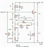
I have simplified the sch to show you what happens in that situation.
At 0 V output the rightmost transistor (T23) can be turned on with 0.65V across the RE 0.09 Ohms. And that activates the protection timer.
But at higher voltages like here 30V, current flows through R38, and causes a small voltage drop across R36, in this case 0.62 mA. So the voltage across RE 0.09 Ohms now has to be 0.65 + 0.62 V = 1.27 V.
At minus voltages D7 just shifts the current flow in R38 to the emitter of T23 instead of the base. But basicly the same happens.
So at 0 V out the circuit trips at 0.65 / 0.09 = 7.2 Amps
and at 30 V out the circuit trips at 1.27 / 0.09 = 14.1 Amps.
So correct SOA slope protection.
Our circuits are actually identical in function, only i have cooked it down in one transistor instead of the usual two.
Attachments
Lars Clausen said:Jan: No no ...
I have simplified the sch to show you what happens in that situation.
At 0 V output the rightmost transistor (T23) can be turned on with 0.65V across the RE 0.09 Ohms. And that activates the protection timer.
But at higher voltages like here 30V, current flows through R38, and causes a small voltage drop across R36, in this case 0.62 mA. So the voltage across RE 0.09 Ohms now has to be 0.65 + 0.62 V = 1.27 V.
At minus voltages D7 just shifts the current flow in R38 to the emitter of T23 instead of the base. But basicly the same happens.
So at 0 V out the circuit trips at 0.65 / 0.09 = 7.2 Amps
and at 30 V out the circuit trips at 1.27 / 0.09 = 14.1 Amps.
So correct SOA slope protection.
Our circuits are actually identical in function, only i have cooked it down in one transistor instead of the usual two.
Lars,
Mmmm... Yes I can see your point. Nifty little circuit. You are correct, it works in the right direction.
What I still don't know is in the situation you show, Vo=30V, what happens with the lower transistor Ic. That lower transistor (T2) in the main schematic) could be carrying current even with Vo=+30V in case you have a complex load (speaker system with xover filter) and this is always the cause of secondary breakdown failure. In the given situation, T2 may be allowed to carry maybe 1 amp max. I don't see how this is protected. The dual circuit takes care of this correctly, of course.
Another thing that bothers me in this circuit is that it looks at the Vo not the actual Vce. That would mean that you need to adjust the component values for each supply value version of the amp, I guess that's what you do? Should work in theory, but I feel more confortable using Vce directly so it is automagically correct.
But my main worry would be with the T2 situation as mentioned above. But maybe I overlooked that too, as you said, it IS weekend
Jan Didden
If you mean that it should be transparent when not activated, yesI fully agree.
yes that's what I mean. It shouldn't affect sonics when inactive. To be more precise an VI-limiter should be inactive when not needed. When the objective stated above is not met, it is most likely because it is not completely inactive.
Hello to Jan-Didden ,
nice to see your SOA slope protection in bipolar amps,
But the case is vastly different in N-channel mosfets as they have no second breakdown voltage with large SOA curve. Your circuit seems pretty good for the SOA protection of Bipolars and i really admire your thinking!
regards,
kanwar
nice to see your SOA slope protection in bipolar amps,
But the case is vastly different in N-channel mosfets as they have no second breakdown voltage with large SOA curve. Your circuit seems pretty good for the SOA protection of Bipolars and i really admire your thinking!
regards,
kanwar
Workhorse,
Yes you are right for MOSFETS you can have something more simple because of the absense of secondary breakdown. That, by the way is one advantage of MOSFETS that is seldom mentioned.
But, to be honest, that circuit comes from mikeks' 2002 series of articles in EW, it is not my own creation. I changed it slightly and added one locus. I think I mentioned that, but I want to make that clear here.
(Don't want to get in trouble in that other thread on copyright etc )
Jan Didden
Yes you are right for MOSFETS you can have something more simple because of the absense of secondary breakdown. That, by the way is one advantage of MOSFETS that is seldom mentioned.
But, to be honest, that circuit comes from mikeks' 2002 series of articles in EW, it is not my own creation. I changed it slightly and added one locus. I think I mentioned that, but I want to make that clear here.
(Don't want to get in trouble in that other thread on copyright etc
)Jan Didden
Jan: You are right this circuit doesn't take care of reactive loads. But like i said in the first post it's a short circuit protection circuit.
And in case of a short circuit the load is not complex It is a short. So there is no phase shift between I and V ....
The other issue is only adressed by using output devices with a relatively high second breakdown point. The SANKEN's used are quite rugged for bipolar devices. Even at high voltages.
(170 W at 80 Volts which would cover for the above example).
I have never heard of one of these amps breaking on grounds of complex load ... And i have sold more than 10k amps with this circuit over the years.
But i guess you are right if you were to take a couple of MJ15XXX something, or the good old BCV64/65 or TIP35/36 and push them to the limit, your slope circuit would be a must. Those devices have no power dissipation tolerance at just slightly over 30V ..
And in case of a short circuit the load is not complex
It is a short. So there is no phase shift between I and V ....The other issue is only adressed by using output devices with a relatively high second breakdown point. The SANKEN's used are quite rugged for bipolar devices. Even at high voltages.
(170 W at 80 Volts which would cover for the above example).
I have never heard of one of these amps breaking on grounds of complex load ... And i have sold more than 10k amps with this circuit over the years.
But i guess you are right if you were to take a couple of MJ15XXX something, or the good old BCV64/65 or TIP35/36 and push them to the limit, your slope circuit would be a must. Those devices have no power dissipation tolerance at just slightly over 30V ..
- Status
- This old topic is closed. If you want to reopen this topic, contact a moderator using the "Report Post" button.
- Home
- Amplifiers
- Solid State
- Output protection