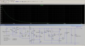
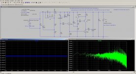
I have been working on this shunt regulator sim and need some help. I started with the 2 transistor regulator of tnt-audio and modified it by adding a ccs everywhere.
Most of the stuff seems to be ok except for the high output impedance (100hz – 3.3R, 1khz – 340mR). I tried a lot of things to fix it, tweaked component values, changed mosfets, transistors, jfet ccs etc, but it just doesnt budge. Trying different stuff improved the ripple, but no change in impedance. Increasing the main ccs current also didnt help with the output impedance. My output load is at 1 khz and the spike at 1khz is also high. Zener current is a little more than the zener test current in the datasheet.
What decides the output impedance of this kind of circuits or how do I improve it.
Attachments
...Most of the stuff seems to be ok except for the high output impedance (100hz – 3.3R, 1khz – 340mR). What decides the output impedance of this kind of circuits or how do I improve it.
A common sign that a parameter (in your case, output impedance) may be getting affected by the value of some capacitor (with respect to it's opposing resistance term) is when that parameter changes by a factor of ten with decade change in frequency.
You did mention that you've tried changing some components but didn't specify which. Did you try increasing the values of C9, C8 and C11?
I don't know your answer.
But I suspect your formula for calculating the output impedance is incorrect.
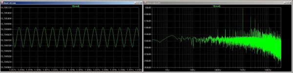
I just tried Vout/1A and changed the response to linear from log to see it in ohms in the ac analysis response.
To start with, you'r driving the gate of the shunt fet from a high impedance.That is a current source an a collector output.Not the best way to get a fast response.
Mona
I tried an emitter follower between the two, didnt change the impedance.
Just tried that, changed all three to 1000uf, no change in impedance.A common sign that a parameter (in your case, output impedance) may be getting affected by the value of some capacitor (with respect to it's opposing resistance term) is when that parameter changes by a factor of ten with decade change in frequency.
You did mention that you've tried changing some components but didn't specify which. Did you try increasing the values of C9, C8 and C11?
Btw the load current source should not swing with 70mA amplitude, that is +-70mA when feeding 100mA=. I set this to 10mA amplitude and 50mA DC offset, thus current swings now between 40 and 60mA (20mApp).
Measuring 30uVpp of 1 kHz ripple gives an output impedance of 1,5mOhm at 1kHz.
Measuring 30uVpp of 1 kHz ripple gives an output impedance of 1,5mOhm at 1kHz.
No - you cannot expect useful simulation results invoking ac-analysis with nonlinear components in your circuit. Transient analysis is the only way!
Well, you can, if you set a DC operating point. Not easy in case of a bridge rectifier though... So I would simply replace it by a voltage source.
And AC analysis is needed for checking stability + freq. dependancy.
My version:

1.6 uVpp, 140 mApp -> 0.011 mOhm @ 1 kHz. I like this game.
")
Last edited:
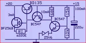
That is an issue, there is no voltage left to be dropped across q3 as the entire Vbe is eaten up by the emitter resistor. I guess that will rule out any bjt based ccs. I have to change it to jfet ccs.And another thing, how do you suppose current source Q3 will work with only 0V6 volts from the b-e junction of Q1 ?
Mona
I have only 5 comment for this:
Emitter resistor dont have to be that high (if you use current mirror).
Most jFETs need much higher voltage to be current generator.
Emitter of next transistor can be rised with a diode.
The whole current generator is a waste of time, a resistor is perfectly enough. Not joking!
2 zeners in serial, with the raised emitter gives lower impedance, noise and temperature dependency.
What decides the output impedance...
Rout=Ugs/dId/(voltage gain). Roughly.

You are right about that, I removed most of them and got pretty decent results. The gain stage ccs seems to make quite a lot of difference so I have retained it. Emitter follower is giving me a few db, will try to get rid of it next.The whole current generator is a waste of time, a resistor is perfectly enough. Not joking!
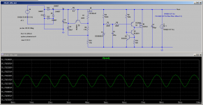
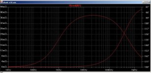
Taking out the bridge rectifier fixed the issue with output impedance graph. I get about 105uR at 1khz and 1.5mR at 20khz. I am not so sure about the phase, is there any issue with that.
Attachments
Last edited:
Try to simulate like this, that is my shunt symmetric PS. Use .ac not .tran for that
Maybe some have had problem to open this file, here is the plot.
Attachments
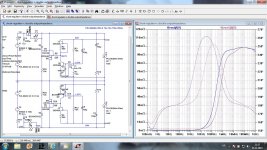
Vout1 has lower output impedance from 20kHz to 40MHz.
Is this because it uses an N channel shunt device?
What's Vout like if the 9540 is swapped to 9610?
I used in this simulation models found in the TLspice library, and it is 9640 not 9540. IRF540/9540 will give lower output impedance, but it is so low already and it will not influence it to much. Impedance between 20k and 40 M depends on output cap ESR. To low ESR will generate peaking.
- Status
- This old topic is closed. If you want to reopen this topic, contact a moderator using the "Report Post" button.
- Home
- Amplifiers
- Power Supplies
- output impedance in shunt reg sim