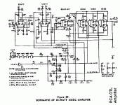
Do I here a need for a new thread...
Steve Eddy sightings
Here's on for you alfredo.
 Right up our alley
Steve is the man
santee
Steve Eddy sightings
Here's on for you alfredo.
Steve is the man
santee
Howdy Mohan,
Was nice to read someone else has had succes with the 6c41!
Obviously as this is a commercial design, so you might not want to divulge all the tricks of your trade..so to speak.
But what operating point did you use for the 6c41? And what did you use to drive the tubes?
Regards,
Bas
Was nice to read someone else has had succes with the 6c41!
Obviously as this is a commercial design, so you might not want to divulge all the tricks of your trade..so to speak.
But what operating point did you use for the 6c41? And what did you use to drive the tubes?
Regards,
Bas
REALLY OLD STUFF.
Hi,
If you replace the 6082's with 6080's,the first tube with a 12AX7
then the second with a 6SN7 you'll get pretty close to the circuit as presented by Bruce Rosenblitt in Glass Audio.
From that standpoint,yes I built it although with 8 output tubes.
Sounds very good too.
Don't forget that the circuit you show was optimized for a 16R loudspeaker though.
Cheers,
OTL
Hello,
Yes,but are your Altecs 8 Ohm?
Or maybe you don't want to build this for yourself?
The reason I upped the tube count was also that my customer had lower effeciency speakers then recommended by Bruce R.
If you like I can e-mail you the B.R. circuit.
Cheers,
Hello,
Eight output tubes, to lower the output impedance more?
Yes,but are your Altecs 8 Ohm?
Or maybe you don't want to build this for yourself?
The reason I upped the tube count was also that my customer had lower effeciency speakers then recommended by Bruce R.
If you like I can e-mail you the B.R. circuit.
Cheers,
OTL
Hi,
Sure Joel,no problem.
I suggest you take a look at schematics on the Bonavolta site:
OTL 6AS7G
Also,since you have such high efficiency speakers,it may be interesting to experiment with a full class A design.
That is if you care about that of course.
Cheers and don't hesitate to ring the bell,
Hi,
Sure Joel,no problem.
I suggest you take a look at schematics on the Bonavolta site:
OTL 6AS7G
Also,since you have such high efficiency speakers,it may be interesting to experiment with a full class A design.
That is if you care about that of course.
Cheers and don't hesitate to ring the bell,
Re: OTL
What wattage output are we talking about? I only need under 2W. Do you have a class A design in mind?
fdegrove said:Also,since you have such high efficiency speakers,it may be interesting to experiment with a full class A design.
What wattage output are we talking about? I only need under 2W. Do you have a class A design in mind?
OTL
Joel,
You're looking at at least 40W when you use the 6080s.
Sorry for stating the obvious but with OTL amps you just can't have it both ways:
You need low output impedance so in order to get that you need to add tubes in paralel.
After that you apply a global feedback loop,including the speaker to get a fraction of the tubes combined Ri.
I mentioned a class A operation since it is rather uncommon in OTL designs and you have the speakers that match the ticket.
Most OTL amps operate in class AB since x-over distortion isn't a big issue here there is no OPT.
Not really but it can't be too hard to bias the tubes for class A.
I do stress that it is NOT at all a requirement,it was just a thought.
Ciao,
Joel,
You're looking at at least 40W when you use the 6080s.
Sorry for stating the obvious but with OTL amps you just can't have it both ways:
You need low output impedance so in order to get that you need to add tubes in paralel.
After that you apply a global feedback loop,including the speaker to get a fraction of the tubes combined Ri.
I mentioned a class A operation since it is rather uncommon in OTL designs and you have the speakers that match the ticket.
Most OTL amps operate in class AB since x-over distortion isn't a big issue here there is no OPT.
Do you have a class A design in mind?
Not really but it can't be too hard to bias the tubes for class A.
I do stress that it is NOT at all a requirement,it was just a thought.
Ciao,
Mohan Varkey, how are you coming along?
I'm very interested in an SE OTL design that is of a reasonable scale and complexity.
Also, the lack of a coupling cap at the output on all the designs I've seen scares me. I have visions of my 30 year old Altec's burning up because of a wiring error, or part failure.
I'm very interested in an SE OTL design that is of a reasonable scale and complexity.
Also, the lack of a coupling cap at the output on all the designs I've seen scares me. I have visions of my 30 year old Altec's burning up because of a wiring error, or part failure.
SCARE CROW
Joel,
You do run a test before you hook anything up to your system,don't you?
At least a dozen of friends of mine have built OTL PP amps,none of them has ever had DC on the output.
Personally I can garantee it is just impossible,I will even pull an entire bank of tubes in public and it still won't have any DC on the output.
It only shows a lack of understanding of OTL circuits if people have that kind of fear.
OTOH,with your speakers you could just as well listen to music throug... a Black Gate cap,perhaps?
I know,I can be mean,
Hello everyone,
Hope you all had a nice family get together at Christmas. Best wishes for the New Year.
Fred, thanks for encouraging me. I need new topologies that we could consider for an OTL.
I do not want to follow the Futterman, Technics, Circlotron etc. etc. topologies. This is why I opted to look into SE topology. Ideas on lowering output impedance without too much feedback is what I am looking for. Simply post some thoughts. No circuits are needed at this stage. Just a description of what you have in mind will do.
I have been waiting for the apple to fall on my head. Because of the rather dry and extended summer, this side of the equator, there are not many apples on my tree. Same with the lemon tree as well. In previous years, we used to take bags of fruits to the church!!!!
Bas, a good operating point for the tubes is 150V measured from Cathode to Anode and 150mA plate current. I use one of my favourite tubes, Raytheon 417A for the front end. The amplifier is DC coupled. I have now rewired the power supply. Ripple is now reduced to 3mVpk-pk. This is a Signal to Noise ratio of 80dB. The B+ winding is 340VA. 1.2A chokes are rather large. I need help in lifting the amp from Conference room to the Testing room. The prototype looks ugly because the original layout was based on the size of the 500mA chokes. In my usual confident manner, I forgot about the current requirements for a second channel!!
Joel, I have been pretty busy with the design and construction of my transformer coupled SE amp using 6C41C tubes. I apologise for this delayed reply. If you are worried about smoking Altecs, then, you could capacitor couple the output. After almost 3 months of design revisions and implementations, I am beginning to get a grip on the characteristics of this tube. Now it is time to think about SE OTL designs. Your suggestions on possible topologies are most welcome.
Regards,
Mohan
SE OTL.
Hi Mohan,
The day I see a SE OTL without a cap on the output I'll send you,or the inventor a crate of Belgian beer....no,no xformer either.
How can you possibly tap the AC from an SE circuit without having DC as well?
I wonder what rabbit is going to be pulled?
For PP,yes...
Cheers,
Hi Mohan,
The day I see a SE OTL without a cap on the output I'll send you,or the inventor a crate of Belgian beer....no,no xformer either.
How can you possibly tap the AC from an SE circuit without having DC as well?
I wonder what rabbit is going to be pulled?
For PP,yes...
Cheers,
Hello,
I am also interested in building OTL with 6AS7GA Valves.
Does someone have copy of the original article about this OTL
from the Glass Audio 1990, or know where it could be found ?
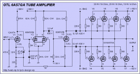
Here is 6AS7GA OTL amplifier schematic.
I redraw it, so it can fit the screen and on
single piece of A4 paper when printing.
I will also redraw power supplies the same way, and post
them latter here and on the my website.
Best regards,
Kristijan Kljucaric
http://web.vip.hr/pcb-design
Attachments
OTL
Hi,
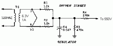
Actually what you do is connecting the B+ of 550VDC to the heaters through a couple of resistors..
By doing so they run at a higher potential with respect to ground.
I replaced the zener diodes in the regulators with a pair of glowdischarge tubes .(OA2 I think)
So,yes pin 3 it is.
I can't seem to find the original article any more,it was explained in there.
All I remember is that the amp had a rotary switch and an ampmeter to verify biasing.
It sholudn't be a problem provided the output tubes are reasonably closely matched.
The current you let flow the more you bias the tubes to class A.
BTB ELECTRONIK
Ask for Frau Thomanek.
If they don't carry it I'm sure this company has stock:
HALFIN INTERNATIONAL
Ask for Mr. Michel Wiams and give him my regards.
Cheers,
Hi,
Also the 'To 550' should be connect to the 6EM7 cathode (pin 3) ?
Actually what you do is connecting the B+ of 550VDC to the heaters through a couple of resistors..
By doing so they run at a higher potential with respect to ground.
I replaced the zener diodes in the regulators with a pair of glowdischarge tubes .(OA2 I think)
So,yes pin 3 it is.
I would like to know a little more about bias adjusting,
I can't seem to find the original article any more,it was explained in there.
All I remember is that the amp had a rotary switch and an ampmeter to verify biasing.
It sholudn't be a problem provided the output tubes are reasonably closely matched.
The current you let flow the more you bias the tubes to class A.
Where to get 6EM7 in Europe ?
BTB ELECTRONIK
Ask for Frau Thomanek.
If they don't carry it I'm sure this company has stock:
HALFIN INTERNATIONAL
Ask for Mr. Michel Wiams and give him my regards.
Cheers,
- Status
- This old topic is closed. If you want to reopen this topic, contact a moderator using the "Report Post" button.


