OK, I have another question. In going through all my junk, I found a can with two 10mh chokes in the same can. I thought that I could use it on this amp the remembered that the PS on the TM OTL does not have chokes. I am use to building SET amps and correct me if I am wrong, but this amp is a PP design is it not? So the ripple does not have to be treated so carefully as a SET amp. Is my thinking correct?
OTL by TIM MELLOW
Hi All,
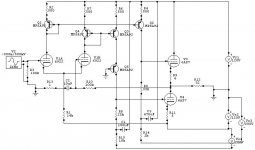
I've attached my quick re-draw of a previous re-draw (!) of the Tim Mellow OTL circuit. Just that I find the 'crossing over' bit (between ECC83's and EF86's) a bit confusing when it comes to construction (just me?) Might help someone? I've not labelled all components as they're on the first re-draw.
Regards,
David.
Hi All,
I've attached my quick re-draw of a previous re-draw (!) of the Tim Mellow OTL circuit. Just that I find the 'crossing over' bit (between ECC83's and EF86's) a bit confusing when it comes to construction (just me?) Might help someone? I've not labelled all components as they're on the first re-draw.
Regards,
David.
Attachments
Ok I am a week in and say a total of 25 hours of listening time. The amp has opened up quit a bit. I now have it back on my DIY Tannoy mono vinyl system with a custom tube preamp and here are my thoughts overall between the DIY Tannoy and the Quad's.
Quads
Clean crisp sound but not to sterile. In general a bit bright certainly when you first turn it in and for several minutes (10 to 20) before she warms up but even then stays that way after it drops a few notches in the bright catagory.
DIY Tannoy
Deeper bass but that is mostly a product of the speaker (front loaded horn) but what she really does is control the bass very well. Less bright but still a bit higher then I would like.
On both the mids are reasonable and stand up well to my NYAL OTL3's but do not surpass or tie them. I think the "Bright" issue is a product of the 12AX7. I will update again over the next few weeks as she burns in more and as I get more time to listen directly.
Be well all.
..... In general a bit bright certainly when you first turn it in and for several minutes (10 to 20) before she warms up but even then stays that way after it drops a few notches in the bright catagory............Less bright but still a bit higher then I would like....... I think the "Bright" issue is a product of the 12AX7.
I agree, and it's also been my experience that that type of sound is a 12AX7 trait, revealed when the rest of the circuit is up to it. A 6SL7 may be a much better choice.
Stuart
I agree, and it's also been my experience that that type of sound is a 12AX7 trait, revealed when the rest of the circuit is up to it. A 6SL7 may be a much better choice.
Stuart
I love the 6SL7 great idea. A little lower on the amplification factor scale (70) but may work. What do see the changes being? I might bite and build it.
Thx
I love the 6SL7 great idea. A little lower on the amplification factor scale (70) but may work. What do see the changes being? I might bite and build it.
Thx
Hey desperateaudio,
The 6SL7 sounds really good at 150V on the plate and ~1.3-1.4mA. Other O/P may sound still better, but I know firsthand that the stated point sounds excellent. Now, within the limits of your build, that may not be possible. The 12AX7, operating at 0.46mA per plate is pretty typical of old school (Marantz 7c, PAS 3x, et. al) thought. Is higher current in the tube better? I don't know. Trouble is, with 146V to play with and a big B- to cover, not many other choices work. Tube CAD says the 1st stage will have a gain of 59.26, but that's for a differential input. SE input gets you half of that or ~29.6.
HF -3dB point is 176kHz, output impedance is 64k.
Simply plugging in the 6SL7, no operating points or other elements changed, reduces stage gain to 47.17/23.6, with a -3dB high cut of ~87kHz and an output impedance of 60.3k. You could just rig up an octal socket and try it out.
If you are willing to build a different 1st stage power supply, you could increase B+ to 280V, change plate resistors to 200k, use a cascode DN2540 or a 10M45S current source in the tail in place of the 470k connected to something a little more manageable like a -12V supply, and change the series input resistor to 5.6k and end up with a gain of 55.4/27.7, -3dB of 177kHz and an output impedance of 101k. I don't think the increased output impedance is an issue since the driven load is over 1M.
I don't know if the feedback resistor needs to be changed.
A few points confuse me
 :
:1) Is not the feedback dependent on the volume pot setting? The 34k seems to be in series with the shunt portion of the volume pot from the perspective of the series feedback resistor.
2) Why is it necessary to have the 1uF and 34k resistor series connected then paralleled with the 1M resistor in the unused grid circuit? If differential input is never to be used, cannot that grid simply be shorted to ground?
3) In the original article, Mr. Mellow referred to an alternate input connection which would negate the input coupling caps. That to me is a very good thing. Has anyone worked out that configuration? Mellow mentioned that differential balance would be thrown off, unless a CCS was used in the differential tail. That wouldn't be a problem for me, since that's how I'd approach it anyway, choosing to forgo a -430V supply and 470k for the -12V supply and a CCS as mentioned above, regardless of input tube.
Stuart
1) Is not the feedback dependent on the volume pot setting? The 34k seems to be in series with the shunt portion of the volume pot from the perspective of the series feedback resistor.
Yes, it is. That's why applying the NFB in that manner is not viable unless the input is buffered. You can get away with it when using op-amps since the Zo of an op-amp is quite low. Otherwise, changing the volume changes the gNFB. Not good.
2) Why is it necessary to have the 1uF and 34k resistor series connected then paralleled with the 1M resistor in the unused grid circuit? If differential input is never to be used, cannot that grid simply be shorted to ground?
It's not necessary unless you need to float the grids above DC ground.
Folks,
Has anyone done a cap coupled SE OTL?
Any circuits around?
Now there's a flavour......
Hugh
See the post #11 at this thread:http://www.diyaudio.com/forums/tubes-valves/169017-6c33c-otl-dc-schematic-needed.html
Good Luck
Yes, it is. That's why applying the NFB in that manner is not viable unless the input is buffered. You can get away with it when using op-amps since the Zo of an op-amp is quite low. Otherwise, changing the volume changes the gNFB. Not good.
It's not necessary unless you need to float the grids above DC ground.
Thanks Miles,
Kind of what I thought.
Stuart
Man do I know how to shut down a thread or what?
Hehe. I seem to have the same effect more often than not
There are a few things I don't like in this circuit which stopped me from further consideration to build one (and following this thread)...NFB looping over two gain stages, high ohm resistors in series with signal, cap at input, 12AX7, EF86, and probably some more if Im in the mood.
The unused input probably has the components equal the used input b/c that's wise in SS where leakage will create unessesary offsets if not equal. I recon the designer is primarily an OPAMP guru...Oh now I'm about to step on some toes...gotta stop...
Saying all this neg I must add I appreciate unusual designs, and Tim Mellow deserves kudos for that. But I'll stick to my own OTL design.
Saying all this neg I must add I appreciate unusual designs, and Tim Mellow deserves kudos for that. But I'll stick to my own OTL design.
SemperFi
Can you point the way to you own OTL design. I love glass houses
SemperFi
Can you point the way to you own OTL design. I love glass houses
Sure.
Here is a version...I like the possibilities current mirrors give, and to me the pros outweigh the cons. (No capacitor, wideband response, gain and bias (of the output tubes) in one, load resistors placed at any voltage level, etc)
For simplicity only a single 6AS7 is shown, and for simulations the load is 32ohms. 4 tubes in parallel is fine for 8ohms.
Many think the cathode resistance in the output is too high, but I've tested and believe it both sounds better, and provides better harmony between the parallel tubes.
The mirrors can be modded in all kinds of ways, cascoded, wilson style, base drive with another pnp's emitter to the mirror bases, etc etc.
The load/gain resistors can be varied without any change in distortion, just gain. U can experiment with various values for max symmetry, but I cannot hear distortion if it is slightly off, since it's all benighn second order.
The bias is adjusted with a potentiometer in series with the LTP tail resistor.
Btw, do u know why a CCS in the tail of the PI is actually worse in this circuit?
Cathode followers driving the output helps increase power, obviously, but I prefer the sound of the lesser powered CF-less version.
I don't use NFB, R13 is not there, but if u like, R13 can be up to 2kohms...actually, u decide, it can be any value...
Attachments
Last edited:
Thought I'd mention...I have been building this type (totempole) OTL the last 10years, but have finally decided to build a circlotron. I like the symmetry at the output...I will of course mod the Atmasphere circuit and use my mirror and DC couple thru out...Unfortunately time is not abundant as usual, so I don't expect anything finished in a while.
For simplicity only a single 6AS7 is shown, and for simulations the load is 32ohms. 4 tubes in parallel is fine for 8ohms.
Nice,
I will probably have several questions but for now my main question is how did you deal with your 6AS7 matching since so many of those tubes just do not have matched triodes in the same envelope?
- Home
- Amplifiers
- Tubes / Valves
- OTL designed by Tim Mellow with 4 6C33C?