For simple copyright issues, nothing stops one from just hand re-drawing a circuit and scanning it (in place of scanning the actual magazine).
Broskie had a blog article once on the BR OTL patent, and what needed fixing (it doesn't even work properly). Putting the bootstrap back to the cathode follower plate, as in the patent, does not equalize the top side (to bottom side) gains. The "earlier art" version does equalize the gains, if the splitter plate bootstrap goes back to one side of a pentode LTP. (the LTP triode splitter with a plate bootstrap is not working so well due to the triode Rp interfering). With un-equal gains between the top and bottom output tube sections, they fight each other, and produce wasted heat, and unnecessary distortion (and really bad distortion if running in class AB with unequal gains).
Broskie had a blog article once on the BR OTL patent, and what needed fixing (it doesn't even work properly). Putting the bootstrap back to the cathode follower plate, as in the patent, does not equalize the top side (to bottom side) gains. The "earlier art" version does equalize the gains, if the splitter plate bootstrap goes back to one side of a pentode LTP. (the LTP triode splitter with a plate bootstrap is not working so well due to the triode Rp interfering). With un-equal gains between the top and bottom output tube sections, they fight each other, and produce wasted heat, and unnecessary distortion (and really bad distortion if running in class AB with unequal gains).
Last edited:
WHAT???
WHY???
Obviously they are shown for educational value. Please let us not start trying to edit ourselves for the sake of making the world safe. We all need to be our own keepers of our safety. After all we are only as safe as we make ourselves, and this means knowing and having access to knowledge of presently "correct" and formerly practiced SOA.
Beside I'll bet there a many of us who routinely restore or work on old "unsafe" radios and test equipment... we even routinely survive! ;-)
Amen brotha

Just to be clear that circuit schematic has been posted here on this forum for quite some time and is on other websites that have scanned pages of books that are now in the public domain to the best of my knowledge. There are also two alternate versions of the schematic one of which has RCA removed from the page.
Not a big fan of BR frankly. Ralph's stuff though is very good, and he's been at it for a very long time.
His site is here: Atma-Sphere Music Systems, Inc. Dragging high end audio (kicking and screaming) into the future!
Very nice. So where can I get a schematic for the Mk. 3.1?
")
Last edited:
Very nice. So where can I get a schematic for the Mk. 3.1?
Atma-sphere OTL Circlotron M60 Mk.ll.3 schematic+descriptions is here:http://www.diyaudio.com/forums/tubes-valves/161112-what-tubes-tube-amp-3.html
Think this AT M60 design suport up to 12 tube 6H13S for output power stage(maybe even 14) for higher output power demand.
All the Best for Everyone and Happy New Year
Does anyone know where the power supply side is?
Does anyone know where the power supply side is?
Not sure did you look for PSU schematic for AT M60 OTL Circlotron Power Amp or something else?(my English is very limited,sory).
Any way,schematic for AT M60 PSU is on the same atached thread link.
Best Regards
Last edited:
Its all on that thread...Does anyone know where the power supply side is?
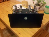
It took a little over 2 years but here it is. Just finished it... sorry but life got in the way.
Enjoy.
VERY nice!!! So is this based on the schematic from 1954 posted earlier in the thread? (Which was due to Dickie and Macovski, I think.)
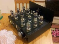
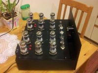
Any chance of a few more photos, underside too?
Chris
VERY nice!!! So is this based on the schematic from 1954 posted earlier in the thread? (Which was due to Dickie and Macovski, I think.)
Any chance of a few more photos, underside too?
Chris
Yes this is the Glen Orr OTL from Audioxpress which was based on the 1950's otl. Glen's design changed the original a good amount though. Had some inside pics but they got lost and getting inside is a real Bit*h as the case started life as a high end sony cd player from the 80's i gutted and shoe horned the amp into. you access the inside from taking off the top an that is the b***h.
Thx for the comment
Im using 6080wc Jan Philips tubes from the 80's on the output. 12ax7s as the 2 first stages and a 7n7 for the driver. Right now I have only the heater voltage on in the pics shown. I will leave the amp on with just heater current for the next several days to just try and prep the tubes for use since they were sitting for years in their boxes.
The reason most OTLs are totem pole is that to reduce the amount of waste heat you need to use push pull. The top half does not conduct while the bottom half is conducting and vice versa. This type of amplifier is nearly always class AB if not class B. Full class a is not impossible, you could warm a large house with the waste heat and need to change the output valves as often as you change your under wear.
There is no opposites valve. What I mean by this is with solid state valve ( MOSFETs) there are P channel and N channel variants and yes a FET is the closest thing to a valve with out being a Thermionic valve. FETs as their name implies rely on two voltage field effecting the conduction of electrons.
The lack of an opposite means you have common anode and common cathode amplifiers configuration which is why you need bruce's circuit to stop degenerative feed back in the amplifer which will affect half the output valve. This is done by creating the 450Volt offset on the anode of V3A with reference to the output.
Bruce ha used 6AS7 and discard them as he had issues with them. He moved on to EL509 and a Russian valve. His latest designs use the EL509 and his most powerful amp give 170 Watts RMS into 8 ohms.
- Status
- This old topic is closed. If you want to reopen this topic, contact a moderator using the "Report Post" button.
- Home
- Amplifiers
- Tubes / Valves
- OTL designed by Glen Orr AudioXpress