I'm a pragmatist. I use tubes because they do many, not all, audio jobs better than SS. Where "sand" works well, I say use it and move on. FWIW, I'd use a lump of galena if it worked well, but it doesn't.
I think think this is a healthy, realistic viewpoint, devoid of Kool-Aid. Kool-Aid kills. Avoid.

..Todd
Latest Versions
All sugested changes should be incorporated in these schematics.
Second Version of Layout complete. This time on CAD so that the topplate can be drilled. I wont have final dimensions on OPT till it arrives the only downside to custom wounds. Once they are in hand it won't take long to make the plates. PT's are in the varnish tank and OPT's should be on winder early next week. Moving right along!!!!! Box of parts starting to get full.
Attachments
There's no way to get 25 to 30 V. by FWCT rectifying 9-0-9. 22-0-22 is more like it. Another option is to bridge rectify 22-0. Also, regulating here is probably a bad idea. If you regulate B+, you need to regulate C- too. Filter WELL and have done with it.
If you go with a dedicated low voltage B+ supply for the FET driver, use IRFBC20s, as their crucial Crss is both low and stable.
If you go with a dedicated low voltage B+ supply for the FET driver, use IRFBC20s, as their crucial Crss is both low and stable.
Also, regulating here is probably a bad idea. If you regulate B+, you need to regulate C- too. Filter WELL and have done with it.
Regulating, or not regulating the drain voltage on a source follower will have no measurable effect on the source voltage. The regulator affords about a 50 db reduction in hum, so it has merit. The PSRR of the source follower is also quite high.
I generally agree that regulation should be applied to the C- (bias) supply if the screen grid supply to the output tubes is regulated. The plate supply has a lesser effect on the tube current, but these are obviously the same supplies in triode or UL mode. In this case the +25 volt supply only goes to the mosfet drains. And yes a 48 vct transformer is probably the best choice.
Corrected Schematics
Please disregard previous schematics. The ones attached have been corrected to reflect current status.
If the Fet source follower has a high PSRR is it critical that the B1+ not be regulated. My thinking was that the LM317 provides a cheap and compact way of a clean voltage for the drains. (not that a CRC wouldn't be effective) I calculated that the drift would be <1V so wasn't initially worried about it. I take it I should be concerned
George, Since I went with a seperate rail, I kept B1+ lower to take advantage of minimizing the chance of spectacular tube failure should the FET fail. Is there a problem at that voltage that I didn't pickup on?
Attachments
A Simple CRCRC filter addresses the issue of regulated B1+. I can get 90uV ripple with the same xfmr and 220uF-220R-470uF-220R-470uF. at right around 38V with 20mA. That is without even tweeking and using pretty much default values in PSUDII
Attachments
Last edited:
George, Since I went with a seperate rail, I kept B1+ lower to take advantage of minimizing the chance of spectacular tube failure should the FET fail. Is there a problem at that voltage that I didn't pickup on?
Not that I am aware of. The fet needs sufficient voltage across it so that the capacitance changes with voltages are minimized. In the critical "first watt" or first few watts of power the voltage across the fet is in the 75 volt range which is good. The IRFbc20 is flat above 20 volts which will only be seen on strong signal transients.
A Simple CRCRC filter addresses the issue of regulated B1+.
Most of my amps use CLC with the L being a common mode choke made from an old transformer. Some have even used simple CRC. I was just pointing out the fact that a regulator here will not cause any unwanted ill effects.
Most of my amps use CLC with the L being a common mode choke made from an old transformer. Some have even used simple CRC. I was just pointing out the fact that a regulator here will not cause any unwanted ill effects.
Did I understand it correctly btw. that you use a 1:1 transformer for this, running the one line through primary and the the other one through secondary? Which transformer size would be the right choice for common PSU application?
I am interested in trying the common mode choke as well. I was thinking as a mod further down the line to get a small 180Vct and a small 1:1 common mode to set up C- and B1+ as tubelab suggested. This should end up +/- 110V approx. Havn't simmed it yet but certainly worth experimenting with. So I have the same question, how do we size the 1:1 xfmr?
George,
Thanks for clarifying. I had calculated that I would see << 1V bias swing with the mains line fluctuating 5%. I wasn't initially worried about that until I read the above and became confused. (easy enough to do for me). I do agree that in principle it is not a great idea. With the PSR as you pointed out, I am now glad to have gone through the exercise of looking at a simple filter for the supply. It is even simpler to implement...
Progress,
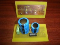
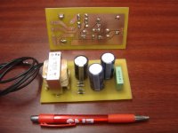
Things are starting to move along, The B1+ rail is complete and tested under load. Holds 36V at 25mA. Ripple was 0.07mV. Not too shabby for a CRCRC filter. Voltage is hotter than expected but certainly welcome. The xfmr is a 4.4Va Hammond. The circuit is built per the attached schematic. The C- filter is also under construction. Won't be able to test that until the PT and choke arrive. I put a pen in the pic for scale.
Things are starting to move along, The B1+ rail is complete and tested under load. Holds 36V at 25mA. Ripple was 0.07mV. Not too shabby for a CRCRC filter. Voltage is hotter than expected but certainly welcome. The xfmr is a 4.4Va Hammond. The circuit is built per the attached schematic. The C- filter is also under construction. Won't be able to test that until the PT and choke arrive. I put a pen in the pic for scale.
Attachments
Last edited:
Further Progress
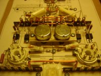
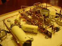
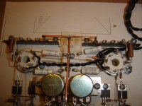
The circuit is starting to take shape. Building both channels on a piece of mdf and will transfer over to the aluminum top plate by unscrewing it and reattaching it. Need to have trannies to finish plate which should be next week. With this method, my hope is that I can keep bith units symetrical and orderly. The FETS tuck nicely between the rails(copper wires) and the kt99 sockets via the top plate. Signal path is kept short and away from other components to minimize stray capacitance.
The circuit is starting to take shape. Building both channels on a piece of mdf and will transfer over to the aluminum top plate by unscrewing it and reattaching it. Need to have trannies to finish plate which should be next week. With this method, my hope is that I can keep bith units symetrical and orderly. The FETS tuck nicely between the rails(copper wires) and the kt99 sockets via the top plate. Signal path is kept short and away from other components to minimize stray capacitance.
Attachments
Last edited:
Hi,
Lundahl chokes can be wired as common mode chokes: http://www.lundahl.se/pdfs/datash/1638.pdf
Lundahl chokes can be wired as common mode chokes: http://www.lundahl.se/pdfs/datash/1638.pdf
Another Update
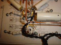
Thought I would update. Work progressing with the limited time I have had recently. All the iron is in the mail so should be here this week.
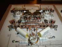
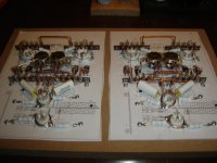
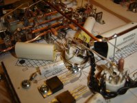
In these photos it shows the heater wiring. Picked up what I could from other thread showing how to run the heater wires. What a PITA as I used 18guage solid core. Please comment if you have suggestions to improve it. All I have left is to run CCS's for LTP and Voltage tube. Hope to have that done in the next few days.
I have been able for the most part to keep to the layout I have drawn. Only a few minor changes in location. Will update that and post once the wiring is complete.
I find it hard to get a good photo that shows the seperation of wires in 3D but they are larger which helps
Thought I would update. Work progressing with the limited time I have had recently. All the iron is in the mail so should be here this week.
In these photos it shows the heater wiring. Picked up what I could from other thread showing how to run the heater wires. What a PITA as I used 18guage solid core. Please comment if you have suggestions to improve it. All I have left is to run CCS's for LTP and Voltage tube. Hope to have that done in the next few days.
I have been able for the most part to keep to the layout I have drawn. Only a few minor changes in location. Will update that and post once the wiring is complete.
I find it hard to get a good photo that shows the seperation of wires in 3D but they are larger which helps
Attachments
Or a power substation. Very nice construction btw.Very industrial! Some of those pics look like an oil refinery.
- Status
- This old topic is closed. If you want to reopen this topic, contact a moderator using the "Report Post" button.
- Home
- Amplifiers
- Tubes / Valves
- OPUS 5.0 A Modern Mullard