Lost another FET after powering down and moving amp to test on main speakers. Must be exceeding Vgs limits either during power down or up. I would think a zener would be appropriate here. Lost only one side of the pair. Nice thing about this is the tube shuts down when it fails.
Any thoughts on this?
Any thoughts on this?
It is playing music now. Tomorrow is a day for measuring and tweeking.
Way too early for impressions other than it has power.... Lots of it. I can clip the output tubes before I clip the driver.
It is very clear and dynamic. Drums are incredible campared to my SET. Curious to see the distortion spectrum... May have to look at that tonight.
B+ is still running about 490V. Plates are not glowing after an hour at 62mA bias.
Best of all no smoke! Just a couple of FETS that went silently in the night before.
I should mention that the above scope pictures were aat the onset of clipping of the driver stage.
A decent design should clip the "finals", before the small signal circuitry clips.
No lack of "stones", as it should be.

Tweak away! Get the residual hum level down. Adjust the phase compensation cap. value, to get a good looking 2 KHz. square wave.
I would think a zener would be appropriate here.
Yes, a zener (or two in series opposing) should be wired from gate to source. I blasted a few IRF830's before I switched to fets with the zeners built in like the Toshiba 2SK3563. I didn't realize that the IR (Vishay) parts still don't have them.
I have some 2sk3564's which I may install tonight. The have 15pF reverse capacitance which is higher than the irfbc20's 8pF. Having the zeners internal to the device should have the lowest capacitance vs. using external zeners.
The 2sk3563's are better than the 64's in regards to reverse transfer capacitance but will have to order them. I don't have any zeners in my box greater than a couple of volts unfortunatley.
The 2sk3563's are better than the 64's in regards to reverse transfer capacitance but will have to order them. I don't have any zeners in my box greater than a couple of volts unfortunatley.
Need some help here. I spent most of the night last night tracking down a very high frequency unstable oscillation.
The problem occurred after I installed the new spec FETS (ended up going back to the original spec during trouble shooting.) Without the KT88's in, I could set bias anywhere I wanted no issue, however once I put the KT88's in I would get up to about 10mA of bias current and then "click", the current would shoot up to 180mA. I used the word "click" because you could hear the tubes click when it started to run away. With the osc scope I could see the drive voltage start to oscillate. Once the oscillation started it couldn't be stopped unless the amp was powered down.
I was able to get the current low enough by biasing direct to the c- rail to measure. At this point I have not hooked up GNFB.
I found that the whole input circuit was oscillating. I dropped input impedance to 50k and problem stopped. I also put 510R carbon comps on all of the tube grids right at the pin. Amp is quite now and plays wonderfully. However not all is quite right.
I find that I have a 1mV RMS very high frequency oscillation (possibly noise) >>50mHz on the input to the kt88 prior to the grid stopper. It does appear on the gate side of the fets but at a much lower level. I was wondering if a ceramic cap on the FET rails would be of value here? Being that my bias circuitry is a pretty high impedance, I am wondering if I am picking up noise from the environment (i.e phones, wireless router etc.) by putting these on the rails to shunt this noise to ground.
I can't see the oscillation/noise on the B+ supply. But the signal is getting back to the input tubes some how, so I plan on increasing the decoupling from the output stage to the LTP and driver on the power supply. I have more than enough drive so losing a few volts of swing will not hurt the amp at all.
Any other things I should persue to clean it up further?
FYI Ripple on B+ is <<1mV
Version 2 Measurements
Amp is doing pretty well now with No Feedback. No stability issues what so ever. I increased the decoupling between output and driver stage which really quieted down the noise I was seeing.
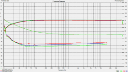
Attached are the latest measurements. Running 485V B+ for output stage and 470V for driver stage.
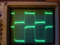
The first is a picture of the THD vs. freq for 50,55, and 60mA Bias. The second is the spectrum at 40W output. and finally a picture of the square wave. top trace is amp and the bottom trace is of input. My signal source isn't great and my 2nd channel on th scope isn't right, I can't calibrate it correctly. The leading edge of the input is really identical to output trace. I won't complain about the scope as it was given to me a while back.
Absolutley NO Hum visable or perceptable.
Added latest schematics as well
Now to add NFB
Amp is doing pretty well now with No Feedback. No stability issues what so ever. I increased the decoupling between output and driver stage which really quieted down the noise I was seeing.
Attached are the latest measurements. Running 485V B+ for output stage and 470V for driver stage.
The first is a picture of the THD vs. freq for 50,55, and 60mA Bias. The second is the spectrum at 40W output. and finally a picture of the square wave. top trace is amp and the bottom trace is of input. My signal source isn't great and my 2nd channel on th scope isn't right, I can't calibrate it correctly. The leading edge of the input is really identical to output trace. I won't complain about the scope as it was given to me a while back.
Absolutley NO Hum visable or perceptable.
Added latest schematics as well
Now to add NFB
Attachments
Last edited:
Excellent progress!!
Would larger R value grid stoppers take care of the oscillations shown on the square wave?
I had ringing on the leading edge of the 10Khz sq wave in my no gfb EL34 triode amp only when changing input amplitude; they would immediately decay at steady state.
Adding grid stoppers took care of the problem completely, although the leading edge is a bit rounded.
Last edited:
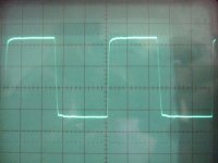
The ringing/oscillations comes from the source. The output is almost identical to the input. The only difference is that the top edge has a slope to it in the output. I need to get a better signal generator!!!! In my latest design update, I did up the value of the grid stoppers to 510 carbon. Maybe I should order some 1k carbon and see if things improve further?
I am in the process of trying employ the feedback to no avail. I need to look at things a little closer tomorrow. I put a 100k pot in instead of the 10k specified. What is weird is that when I drop the resistance to increase the feedback I get more gain, distortion also increases. I checked the input signal and the output signal and both are in phase so technically I should get a reduction in gain. Thinking that my scope may be screwed, I flipped polarity on the OPT and it oscillates wildly at power up. (even at 100k resistance).
Little stumped right now. So instead of messing it up tonight, I stopped, biased in my good Genelex tubes and hooked it into my main system. Incredible!!! The bass vibrates my windows!!!! I am using a SS Rotel on the other channel and there is a clear advantage to the new tube amp. The speaker dissappears. It can almost live without NFB if it didn't have so much gain.
Keep it around 6-9dB NFB when you will successfully close the loop. How much is your measured open loop gain? I use 1k on my KT88s, one or two oscillated if I did not up the value more, but stopped when I used 1k Koa Speer carbon. Its in triode mode. Here is its 10kHz square with feedback loop closed, after Cdom over Rf. 31dB gain, 8.5dB NFB.
P.S. Maybe you need to up the grid stoppers around your input valve too. Maybe you got to adjust your probe too?
P.S. Maybe you need to up the grid stoppers around your input valve too. Maybe you got to adjust your probe too?
Attachments
Maybe I should order some 1k carbon and see if things improve further?
Find some little ferrite beads that will just slip over the leads of the stopper resistor. Put one or two on the leads to the gate of the the fet, and on the grid stopper resistors. A2 and screen driven amps often must run with low value or no stopper resistors, ferite beads are often the only way to tame the oscillations.
Is it the very low source impedance of the source follower driving the high impedance grid that makes it hard to tame it George?
Can it be there is cable inductance to U3,U4? Could be an experiment to make those U3,U4 sources simply resistors if it keeps giving trouble after applying beads?
Can it be there is cable inductance to U3,U4? Could be an experiment to make those U3,U4 sources simply resistors if it keeps giving trouble after applying beads?
Salas,
My open loop gain was 35.3 dB measured with the original grid stoppers. I need to remeasure it with it current set-up.
A couple of notes. My square wave generator is not good. I think I confused the issue by showing the picture of the graph that I did. My input signal from my EMU 0404 sound card rings that badly. I'll try to take the signal off of my calibration post on the osciliscope, That is a nice clean square wave.
Now to the feedback loop. I take it that it will not be easy to get the loop to work, obviously I still have some stability issues to correct. Am I correct in saying that this amp needs feedback that is in phase with the input? Am I also correct in saying that a decrease in the feedback resistor value should net an increase in the feedback. This should in turn result in a reduction of gain.
Perhaps a 100k resistor is too small and as a result I have too much negative feedback when I have the outputs reversed, hense the unstable oscillations.
I havn't disregarded the suggestions above suggesting the use of beads, bigger grid stoppers, and or replacing the CCS's U3,U4 with resistors. The latter I tried already, but it is worth repeating the experiment.
I have the Tracker Pre, almost the same to 404, no good for square waves. Good for FFT. The cal on scope is usually 1kHz & 1MHz switchable for trimming the probe's square. You gonna need 10kHz too for doing better the closed loop sqw smooth out is one thing. But you can do enough on 1kHz.
In phase with the input on 1st stage's grid, opposite on its cathode. They need to destruct to the ratio you set by the resistors where they meet.
When keeping the small one in the cathode steady, the larger the output return (Rf) resistor the less the NFB, the more the gain. The smaller, the less closed loop gain, the more the NFB. Correct.
With 22R you got under the Led I would expect for example just 560R feedback resistor for 28dB gain and 7.3dB NFB remaining from what you got measured (won't change with the stoppers).
10M45S can be nervous even on first stage, you got to check all scenarios. Do the beads that George said etc.
Salas,
Thanks for verifying my reasoning and logic with NFB. It is one thing to read and study it in a book and nice to see that in real life it is correct.
I plan on putting beads in per George's suggestion. I had to order them so they are out a few days. In the meantime while I wait, I will clean everything up and get another good set of measurments on the gain, distortion in each stage etc.
I have a vintage Topward gen, really mediocre but still does it clean VS the card. For tuning squares on valves you need a real gen with some Volt output and low Zo, soundcards don't cut it, they do wiggly squares, noisy if just gens out of software cleaned loop, and need an input protection scheme not to be killed if to FFT probe anodes, power grids, OPTs and stuff. You did well you splashed out on a decent gen. Ebay circa $300?
Right around $300 with warrantee.
Looking for a good distortion analyser as well. Thinking about a HP8903B. The sound card seems to work well, but I question whether all of the (Un calibrated) protection will cause significant error? I am still waiting for parts fo pmillett's sound card interface. They keep pushing back delivery of the op amps.
I just recieved mail that myparts including the beads should be here tomorrow. That was fast.
Thinking about a HP8903B. The sound card seems to work well, but I question whether all of the (Un calibrated) protection will cause significant error?
I use an 8903A. I got it in unwaranteed, but guaranteed to be broken condition for $75. I fixed it then, and twice more since then. It is however an excellent instrument for measuring frequency response, audio voltage (and power using built in math) and THD. By itself it will not tell you anything about the make up of the distortion, or measure IMD. The 8903B is an improved version that uses a different internal processor, but performs the same functions. We still use them by the dozens at work to measure SINAD.
I normally use both the 8903A and a PC sound card, but the second PC died about a year ago and I haven't gotten around to rebuilding it. I got one of Petes interfaces, but haven't built it either. When both the 8903A and the PC were running, the THD numbers matched up pretty well. I was using an Audiophile 2496 card and WinMLS software. I now have a 24192 card for the new PC (Ebay deal).
Thanks Salas and George.
Based on your suggestions, I have updated my schematic to reflect the ferrite beads. I plan on using two beads per lead. I also put in phase of the input and output. After reading Salas comments, I am a little grey on the logic, so I put it in how I have it now. Please let me know if I got the concept correct.
I'll hold back on the audio analyser untill I test the sound card with the function generator. I'll spend the money on a good osc scope.
Attachments
- Status
- This old topic is closed. If you want to reopen this topic, contact a moderator using the "Report Post" button.
- Home
- Amplifiers
- Tubes / Valves
- OPUS 5.0 A Modern Mullard