Personally I prefer it to previous. The ''oh so little more or less'' leave it for later when in stereo and familiar for listening for it too. I see a tilt to the right of the top? Can you close the time scale a bit and show? Also the cap types will do a bit of a difference for fine value choice.
Unfortunately, I already took it off the bench and inserted it into my system. I am allready there in regard to leaving any other fine tweeks for later when the other channel is together.
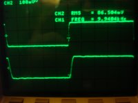
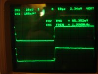
What do you mean by tilt? I do have a decay of the top and bottom of the square wave. You can see it in my earlier posts, particularly on the lower frequencies. That seems to be deeper in the amp as it is there with or without feedback.
I was refering to posts 157 and 159
Also the type of cap is a 680pF poly and a 47pF Silver mica on top of a metal film 1.47k 1/4W. I didn't have any high value silver micas so I figured poly was better than nothing.
Last edited:
I mean the flat top of the square wave leaning to the right. FFT it for 20Hz to 20kHz or more with pink noise and 1/48 octave or white noise and full Log on a dummy load at a point so we know if its extending OK. The caps are cool, I just wanted to know they aren't less than CG0 ceramics.
Ok, I will run the white noise tomorrow. I have cleaned up for the night.
I did run a quick sweep on it before I moved it, and saw the output drop off just north of 100kHz. That was just a qualitative test no numbers recorded.
I do have ceramics!!! Should I use them?
Just kidding.
P.S. Salas, Thank you for the very educational and insightfull dialog.
I did run a quick sweep on it before I moved it, and saw the output drop off just north of 100kHz. That was just a qualitative test no numbers recorded.
I do have ceramics!!! Should I use them?
Just kidding.
P.S. Salas, Thank you for the very educational and insightfull dialog.
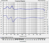
Speakers are scan speak 18M 12 and 2904 4Ohm Attached is the impedance curve of them. Pretty easy load.
iirc, I did try at power and I don't recall any difference. Again that is speculation on a foggy memory so I will see tomorrow.
Thanks on the equip. Makes a huge difference trying to do this stuff even when still trying to learn them.
iirc, I did try at power and I don't recall any difference. Again that is speculation on a foggy memory so I will see tomorrow.
Thanks on the equip. Makes a huge difference trying to do this stuff even when still trying to learn them.
Attachments
On just 6.5inch you will possibly be OK with such feedback. Interesting is that I use triode KT88 on English AN trafos, you use UL on American, plus Mosfet followers, me 12AY7 in, you 12BH7, and we prefer 8.5dB NFB and find 720p comp cap best. Weird. I use a different way to get the same 4.3K PP. I load a 4 Ohm speaker on the 6K OPT's 8 Ohm sec tap.
Attachments
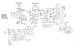
In my case, I set the feedback to set the gain to match the Rotel SS amp I am using for the other channel. I didn't really have a set number. I did know that I didn't want alot since I was running in UL with the "potential" for AB2 operation hence the lower mu on the driver tube. I didn't really want to go to the next OPT core size... It turns out that this sounds good so I left it. I may play with it later after both channels are running and the Honey Do list done.
Early on, my calculations showed that I would end up with about 10dB which would match the gain of my Aleph 5, however I put that amp on another system as it takes so long to heat up.
Early on, my calculations showed that I would end up with about 10dB which would match the gain of my Aleph 5, however I put that amp on another system as it takes so long to heat up.
Comfortably I made 95dB speakers with PHL midranges so 20W are OK and I could triode it. The Scans will appreciate the source followers and UL.
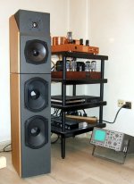
I gutted a donor Korato case, had the Audionote OPTs on, made it there, but I have to match the wood color at a point (I am lazy, i.e. never).
I gutted a donor Korato case, had the Audionote OPTs on, made it there, but I have to match the wood color at a point (I am lazy, i.e. never).
Attachments
Very nice Salas. I have similar issues and find myself in similar problems of what I want to do and what I do end up doing...
Attached are my speakers and the freq responce. I couldn't find the resp curve where the bass was stiched in but this will do.
Attached are my speakers and the freq responce. I couldn't find the resp curve where the bass was stiched in but this will do.
Attachments
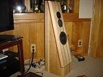
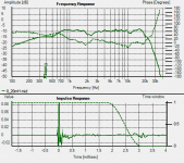
Actually that response curve is prior to the final itteration of the crossover. I cannot find my measurement data of the final version That file has alot of measurements that I want to keep. Although I still have a dip, it is <<3dB today. This set-up is "temporary" as I desire to at least biamp the system. I am looking forward to SY and Pete's xover.
I haven't checked room response yet as I had to compromise on the system's location to obtain family approval. I am sure the standing waves are dismal.
That file has alot of measurements that I want to keep. Although I still have a dip, it is <<3dB today. This set-up is "temporary" as I desire to at least biamp the system. I am looking forward to SY and Pete's xover.I haven't checked room response yet as I had to compromise on the system's location to obtain family approval. I am sure the standing waves are dismal.
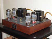
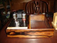
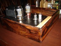
Okay, The weather was just TOO nice today. I couldn;t stay inside and measure, that will have to wait till it rains later. Finally de-winterized my woodshop and got to play with some tools. As a good warm-up I built the two chassis for the amps. The open bay is for the power supply plate. The finish is just seal coat shellac right now. Needs a few more coats, sanding, and then lacquer.
The joints are blind dove tails, with the white strip to be the home of the name plate. Enjoy
Happy Easter
The joints are blind dove tails, with the white strip to be the home of the name plate. Enjoy
Happy Easter
Attachments
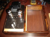
Your perception is similar to mine in regard to the 12bh7. The design was a function of maintaining symmetry and keeping signal path as short as possible. While trying not to violate MJ's construction suggestions too badly...
The 5867 tube is the same size, but that will go in later.
The 5867 tube is the same size, but that will go in later.
- Status
- This old topic is closed. If you want to reopen this topic, contact a moderator using the "Report Post" button.
- Home
- Amplifiers
- Tubes / Valves
- OPUS 5.0 A Modern Mullard