youtube Contiuuo/Cantus Video
Continuo/Cantus - YouTube
Back in production with some refinements for those who would rather buy than build.
Best regards Moray James.
Continuo/Cantus - YouTube
Back in production with some refinements for those who would rather buy than build.
Best regards Moray James.
Continuo/Cantus - YouTube
Back in production with some refinements for those who would rather buy than build.
Best regards Moray James.
Moray, How about a link where we can find out more about the refinements. The YOUTUBE link doesn't give any info at all about this. I haven't found anything on the web yet. Thanks
BillG
improvements on Cantus/Continuo
Hi guys,
Firstly please understand that in no way is this posting intended to undermind or minimize Bosse Hanssons' work or his designs.
A little about me: Rather than classify myself as an "originator", I have been best described as an "innovator". I have the ability to visualize problems and can often offer up a sound solution quickly (not bragging, this just happens to be my "gift", as others may be gifted creatively or mathematically, etc. Ask Moray and others for verification if you like). This is the realm I feel most comfortable in.
The link Moray provided shows a "reference" over-sized Continuo turntable and a Cantus tonearm. But no "improvements" are shown. This the personal turntable of the new owner of the Continuo and Cantus brands, Håken Agborg. Håken had previously been making the wood Continuo turntable plinths for Bosse. After Bosse' untimely death, and his estate was settled, Håken purchased the parts inventory and designs from the estate.
I have been working with Håken (I had started discussing my involvement with the Continuo and Cantus with Bosse prior to his passing) regarding the North American construction of the turntables, as many plinths become destroyed or damaged when being shipped here.
All the improvements to the Continuo turntable are really "refinements" rather than wholesale improvements and are a result of Håken's work. He is the first to recognize that he is not a mechanical engineer, nor an electrical one. In some aspects it is this very fact that can be his greatest strength and his greatest weakness. At least he is willing to recognize the need for improvement. Some of the improvements made thus far are:
Considerations for improving the Cantus tonearm are provisional at best. These include an improvement to the operation of the cuing mechanism (if not already done). I think that with some more work, a refined Cantus would place this arm a significant step up in user-friendliness, and thus acceptance in the more general "audiophile" circles and bring it up to the expected levels of convenience and performance. Currently the arms are glued to the top of the plinth. I think this should be changed. Also adjustments to the Cantus could be easily improved and could provide a simple "retro"-fit to existing arms. I also think an improvement to the counterweight scheme should occur. I have looked at Moray's example and must say that at best it (the counter-weight) is a little suspect. No huge "redesign, just a refinement to the existing product.
I am a little dismayed that these details are still this rough after 30 years or so since Bosse first introduced the Continuo .
My intention is to remake the turntables here (the hard parts) and finesse them so that the bearings are "matched" one to one, the tonearms operate the way they should (or build a custom version from scratch), and make the improvements to the arms and the plinths so that good delivery condition can be assured and sample to sample variance is minimized. If unable to accomplish this with the existing parts I would check into having a new bearing made here, and would use that. The motors are very good ones, and have been used in some very expensive turntables to good effect. I am also looking into a means to control the voltage frequency to ensure rock solid performance with as little fuss as possible.
Make no mistake the underlying principles used in the original designs are very good. It is the sample to sample variance that must be improved, so I guess what one would describe as an improvement in quality assurance (which is designed into a process) rather than quality control (which looks at manufacturing errors and resolution after errors have been made).
Hi guys,
Firstly please understand that in no way is this posting intended to undermind or minimize Bosse Hanssons' work or his designs.
A little about me: Rather than classify myself as an "originator", I have been best described as an "innovator". I have the ability to visualize problems and can often offer up a sound solution quickly (not bragging, this just happens to be my "gift", as others may be gifted creatively or mathematically, etc. Ask Moray and others for verification if you like). This is the realm I feel most comfortable in.
The link Moray provided shows a "reference" over-sized Continuo turntable and a Cantus tonearm. But no "improvements" are shown. This the personal turntable of the new owner of the Continuo and Cantus brands, Håken Agborg. Håken had previously been making the wood Continuo turntable plinths for Bosse. After Bosse' untimely death, and his estate was settled, Håken purchased the parts inventory and designs from the estate.
I have been working with Håken (I had started discussing my involvement with the Continuo and Cantus with Bosse prior to his passing) regarding the North American construction of the turntables, as many plinths become destroyed or damaged when being shipped here.
All the improvements to the Continuo turntable are really "refinements" rather than wholesale improvements and are a result of Håken's work. He is the first to recognize that he is not a mechanical engineer, nor an electrical one. In some aspects it is this very fact that can be his greatest strength and his greatest weakness. At least he is willing to recognize the need for improvement. Some of the improvements made thus far are:
- a rear aluminum plate for connections and manufacturing information
- the use of good quality RCA connectors and ground lug to allow the use of the end-user's interconnects
- the re-routing of tonearm wiring to an internal passageway(which could easily be changed to allow the use of any tonearm in the 9"-10.5" effective length size range)
- the addition of an IEC AC inlet
- a change to a different style of on/off switch (which may or may not be an improvement of any sort)
Considerations for improving the Cantus tonearm are provisional at best. These include an improvement to the operation of the cuing mechanism (if not already done). I think that with some more work, a refined Cantus would place this arm a significant step up in user-friendliness, and thus acceptance in the more general "audiophile" circles and bring it up to the expected levels of convenience and performance. Currently the arms are glued to the top of the plinth. I think this should be changed. Also adjustments to the Cantus could be easily improved and could provide a simple "retro"-fit to existing arms. I also think an improvement to the counterweight scheme should occur. I have looked at Moray's example and must say that at best it (the counter-weight) is a little suspect. No huge "redesign, just a refinement to the existing product.
I am a little dismayed that these details are still this rough after 30 years or so since Bosse first introduced the Continuo .
My intention is to remake the turntables here (the hard parts) and finesse them so that the bearings are "matched" one to one, the tonearms operate the way they should (or build a custom version from scratch), and make the improvements to the arms and the plinths so that good delivery condition can be assured and sample to sample variance is minimized. If unable to accomplish this with the existing parts I would check into having a new bearing made here, and would use that. The motors are very good ones, and have been used in some very expensive turntables to good effect. I am also looking into a means to control the voltage frequency to ensure rock solid performance with as little fuss as possible.
Make no mistake the underlying principles used in the original designs are very good. It is the sample to sample variance that must be improved, so I guess what one would describe as an improvement in quality assurance (which is designed into a process) rather than quality control (which looks at manufacturing errors and resolution after errors have been made).
Moray, How about a link where we can find out more about the refinements. The YOUTUBE link doesn't give any info at all about this. I haven't found anything on the web yet. Thanks
BillG
Bill: you can contact Hakan directly and please send my best regards Moray James.
email address for Hakan: ny.snick@telia.com
Ball Point Tube
Hi Doug,
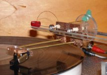
What you been up to all week? I found a couple of dead ball point tubes. They are reasonably thin wall but made of brass. Shouldn't make too much difference. Cleaning out all the old ink is the worst part of the job. Acetone does a good job. You do need an eye dropper and an adapter so you can flush the tubes or some sort of syringe. Then I forced out the crimp they put in the tubes to hold the spring in position. Last was to find a bunch of scrap to build up a test carriage. Pretty much copied the Cantus design with some changes for convenience. What can I say, it works. Used a lot of care to eliminate drag in the bearings. If they are too tight fitting on their mounts, thy will not roll freely. The attached pic shows the junk yard special in all its glory. Used the bearings with the ceramic balls. Put it all together in a few hours. Tested it first with an old Shure cartridge. My care paid off or so I thought because all my groove skipping was gone. I didn't like the sound of that cartridge, but nothing new here. Carriage worked well. Then I put the Audio Technica Signet. Back came the great sound and the groove skips. Taking a clue from the Shure I wondered if it could be the stylus on the AT giving grief. Found 2 old Empire carts and one bent cantilever with what looked like a nice diamond in the junk from a yard sale. A little care and the bend went away. Mounted the first one. It was much better than the AT but I didn't like the sound. Tried the second one, a model 2000 E-3. BINGO. Sound was as good if not better than the Signet. The skipping problems were gone too. I'm delighted so far. It sure would be nice to know what is going on here. Now to do up a nice one.
BillG,
That's great news. Welcome back.
I like the idea of metal ball point pen tubes, especially a trio. Might work very well and could look good, too. A guy at a local kite shop gave me a piece of carbon fiber kite spar about 4.8mm OD x 2.5mm ID. Should work well for Moray's twin tube suggestion. I got to see a "Bird Cage" in action at Riverside in about 1960. The power to weigh ratio made it fast as hell, but just a tad squirrelly.
Did you get a chance to check out the program Jan Didden (janneman) linked to? There are more than a few eff mass and res calculators, but this is the first one I've seen that looks like it might be applicable to LTs.
Hi Doug,
What you been up to all week? I found a couple of dead ball point tubes. They are reasonably thin wall but made of brass. Shouldn't make too much difference. Cleaning out all the old ink is the worst part of the job. Acetone does a good job. You do need an eye dropper and an adapter so you can flush the tubes or some sort of syringe. Then I forced out the crimp they put in the tubes to hold the spring in position. Last was to find a bunch of scrap to build up a test carriage. Pretty much copied the Cantus design with some changes for convenience. What can I say, it works. Used a lot of care to eliminate drag in the bearings. If they are too tight fitting on their mounts, thy will not roll freely. The attached pic shows the junk yard special in all its glory. Used the bearings with the ceramic balls. Put it all together in a few hours. Tested it first with an old Shure cartridge. My care paid off or so I thought because all my groove skipping was gone. I didn't like the sound of that cartridge, but nothing new here. Carriage worked well. Then I put the Audio Technica Signet. Back came the great sound and the groove skips. Taking a clue from the Shure I wondered if it could be the stylus on the AT giving grief. Found 2 old Empire carts and one bent cantilever with what looked like a nice diamond in the junk from a yard sale. A little care and the bend went away. Mounted the first one. It was much better than the AT but I didn't like the sound. Tried the second one, a model 2000 E-3. BINGO. Sound was as good if not better than the Signet. The skipping problems were gone too. I'm delighted so far. It sure would be nice to know what is going on here. Now to do up a nice one.
Attachments
Last edited:
Well done, Bill.
Looking at your image, I wondered what would happen if you replaced the two bearings with a long hollow water-tight float, and filled the V-shaped with a liquid of ideal viscosity. Could you make a floating carriage with in-built damping?
Fantasies aside, you're making this project increasingly difficult to ignore.
Terry
Terry: what makes the Cantus such a good arm is the restricted amount of motion it allows, sideways along the track and very little vertical. This means that more of the energy generated by the motion of the cantilever/coils can be turned into electrical energy. This is how Bo explained it to me. So you can see that a floating arm will have many issues. I expect that this is also why a good mechanical system should sound better than an air bearing. Best regards Moray James.
Bill: nice work. Would you be interested in building an second experimental carriage set up? This time with the two arm tubes parallel and glued together with instant glue. This should provide a much stiffer and better damped arm assembly which should make a noticeable difference. It would be nice to know if the theory holds true and that a light stiff arm is really the order of the day. Best regards Moray James.
Bill: nice work. Would you be interested in building an second experimental carriage set up? This time with the two arm tubes parallel and glued together with instant glue. This should provide a much stiffer and better damped arm assembly which should make a noticeable difference. It would be nice to know if the theory holds true and that a light stiff arm is really the order of the day. Best regards Moray James.
Last edited:
Terry: what makes the Cantus such a good arm is the restricted amount of motion it allows, sideways along the track and very little vertical. This means that more of the energy generated by the motion of the cantilever/coils can be turned into electrical energy. This is how Bo explained it to me. So you can see that a floating arm will have many issues. I expect that this is also why a good mechanical system should sound better than an air bearing. Best regards Moray James.
Bill: nice work. Would you be interested in building an second experimental carriage set up? This time with the two arm tubes parallel and glued together with instant glue. This should provide a much stiffer and better damped arm assembly which should make a noticeable difference. It would be nice to know if the theory holds true and that a light stiff arm is really the order of the day. Best regards Moray James.
Moray, Thanks and sure. I would question whether the difference would truly be significant enough to notice and whether or not the difference would be discernible if the two tubes wide spaced were coated with super glue. They would have to be for any valid conclusions to be made. Find me some tubes to use. The brass pen refills cost a bit much and are far too messy to clean out for me to want to clean more of them.
Rgds,
BillG
Let me see what I can find. Not sure if I follow what you said so perhaps I was unclear. I meant that the two tubes would be side by side touching with a thin line of instant glue to bond them together as one piece so the will be stiffer and will damp each other. I will get back to you with my findings probably early next week. I have a bunch of work to do and I am tied up with that for the moment. You could simply leave the ink in the tubes and seal off the open ends with something yes a little more weight but the ink will damp the tube. Just a thought. Best regards Moray James.
PS can you show a picture of your counter weight on this latest version?
PS can you show a picture of your counter weight on this latest version?
Terry: what makes the Cantus such a good arm is the restricted amount of motion it allows, sideways along the track and very little vertical. This means that more of the energy generated by the motion of the cantilever/coils can be turned into electrical energy. This is how Bo explained it to me. So you can see that a floating arm will have many issues. I expect that this is also why a good mechanical system should sound better than an air bearing. Best regards Moray James.
I wonder if that is really the case? I would have thought that, given the tiny mass and high compliance of the stylus+moving parts, the relatively large mass and moment of the cartridge+arm+counterweight would provide more than enough inertia to keep the cartridge body effectively still at audio frequencies. I guess it wouldn't be impossible to test that.
But I concede that my "floating boat" concept might run into a lot of snags!
Terry
Let me see what I can find. Not sure if I follow what you said so perhaps I was unclear. I meant that the two tubes would be side by side touching with a thin line of instant glue to bond them together as one piece so the will be stiffer and will damp each other. I will get back to you with my findings probably early next week. I have a bunch of work to do and I am tied up with that for the moment. You could simply leave the ink in the tubes and seal off the open ends with something yes a little more weight but the ink will damp the tube. Just a thought. Best regards Moray James.
I wonder though if the triangulation provided by the two tubes being separated and having a wide "wheelbase" is important to provide great stiffness in the horizontal plane? Any tendency to flex in the horizontal plane might promote tracking issues?
I don't suppose we have a detailed technical drawing anywhere of one of these arms?
There appears to be an alarming amount of unshielded audio wiring at the tail end of the arm in these arrangements. Do these arms assume the use of a balanced input pre-amp to cancel hum pickup, or do serious aficionados run their homes on filtered and regulated 12V DC?
Terry
Hi Terry and Moray,I wonder though if the triangulation provided by the two tubes being separated and having a wide "wheelbase" is important to provide great stiffness in the horizontal plane? Any tendency to flex in the horizontal plane might promote tracking issues?
I don't suppose we have a detailed technical drawing anywhere of one of these arms?
There appears to be an alarming amount of unshielded audio wiring at the tail end of the arm in these arrangements. Do these arms assume the use of a balanced input pre-amp to cancel hum pickup, or do serious aficionados run their homes on filtered and regulated 12V DC?
Terry
Just had a discussion on the stiffness topic with my upper classman architecture student (son) and regular tutor on structures. He points out that the two tubes glued constitutes a beam whilst the wide spaced two tube triangular (truncated) is a truss which should give the greater stiffness. Without numbers it is all educated guessing though. Then there is the issue of terminating the ends of the structure and what that does to vibrations. The driver of this structure is the stylus in the groove providing horizontal force. In the case of the beam it is trying to bend the beam. For the truss the force is trying to extend one side member and compress the other. Son feels that this is the stiffer structure. For myself I would expect that the truss could allow thinner material in the tube walls for the same stiffness and strength.
Moray, The fancy counterweight is a scrap off the bench. It started life as the disk element which supports the arm and is immersed in silicone fluid in a WellTempered arm. It is Perspex about 1/4" thick and just happened to balance the cartridge, so I used it as is. Re leaving the ink in the tube for damping: UGGGHHHH, messy bessey, but it would work.
Terry, Needing nice flexible wire and wanting to use what was on hand I use approximately #32-34 enameled magnet wire. I make two twisted pairs of a not too tight a pitch. Twist one pair CW and the other ACW. Then I twist them together even looser. Strangely enough by paying close attention to ground loops and keeping them away from stray AC fields the hum pickup is pretty near nothing even at full amp gain. That's the story there, single ended all the way.
I think I covered everything, will go back and check your posts and do an edit if I forgot anything.
Rgds, BillG
Let me see what I can find. Not sure if I follow what you said so perhaps I was unclear. I meant that the two tubes would be side by side touching with a thin line of instant glue to bond them together as one piece so the will be stiffer and will damp each other. I will get back to you with my findings probably early next week. I have a bunch of work to do and I am tied up with that for the moment. You could simply leave the ink in the tubes and seal off the open ends with something yes a little more weight but the ink will damp the tube. Just a thought. Best regards Moray James.
PS can you show a picture of your counter weight on this latest version?
Moray,
Yes I followed you on the two tubes glued together. For my first go with thin tubes I wanted to stay with Bo's design for starters. See #472 for more details.
BillG
Hi to All,
I've been following this thread from the beginning and have been wondering as to wether the tube in which the Cantus carriage travels, is slanted slightly downhill to aid tracking, or will the Arm track correctly with the tube perfectly horizontal?
Sincerely,
Ralf
I've been following this thread from the beginning and have been wondering as to wether the tube in which the Cantus carriage travels, is slanted slightly downhill to aid tracking, or will the Arm track correctly with the tube perfectly horizontal?
Sincerely,
Ralf
Level?
BillG
Hi Ralf, What I understand is that the original designer, Bo Hansson, ran them level. Scuttlebutt has it that that many users use a slight downward tilt for a bit of help from gravity. I set mine up level horizontaly. Tried a slight tilt but see no advantage. Thanks for joining in.I've been following this thread from the beginning and have been wondering as to wether the tube in which the Cantus carriage travels, is slanted slightly downhill to aid tracking, or will the Arm track correctly with the tube perfectly horizontal?
Sincerely,
Ralf
BillG
Hi Terry and Moray,
Just had a discussion on the stiffness topic with my upper classman architecture student (son) and regular tutor on structures. He points out that the two tubes glued constitutes a beam whilst the wide spaced two tube triangular (truncated) is a truss which should give the greater stiffness. Without numbers it is all educated guessing though. Then there is the issue of terminating the ends of the structure and what that does to vibrations. The driver of this structure is the stylus in the groove providing horizontal force. In the case of the beam it is trying to bend the beam. For the truss the force is trying to extend one side member and compress the other. Son feels that this is the stiffer structure. For myself I would expect that the truss could allow thinner material in the tube walls for the same stiffness and strength.
Moray, The fancy counterweight is a scrap off the bench. It started life as the disk element which supports the arm and is immersed in silicone fluid in a WellTempered arm. It is Perspex about 1/4" thick and just happened to balance the cartridge, so I used it as is. Re leaving the ink in the tube for damping: UGGGHHHH, messy bessey, but it would work.
Terry, Needing nice flexible wire and wanting to use what was on hand I use approximately #32-34 enameled magnet wire. I make two twisted pairs of a not too tight a pitch. Twist one pair CW and the other ACW. Then I twist them together even looser. Strangely enough by paying close attention to ground loops and keeping them away from stray AC fields the hum pickup is pretty near nothing even at full amp gain. That's the story there, single ended all the way.
I think I covered everything, will go back and check your posts and do an edit if I forgot anything.
Rgds, BillG
Regarding the stiffness issue, I think we are missing something. Since the back end of the armwand terminates in very free rolling bearings any force in the horizontal direction simply causes the carriage to move sideways instantly relieving the force. As long as the arm is stiff enough that it can support its own weight all is golden.
New subject: Being sick of trying to guess and set the VTF I hit on this idea last night. Set the counterweight so the stylus just grazes the record. Let it just hit the top of a small warp. Do this with the record playing. Jiiggle the headshell a bit to be sure the bearings are centered in their races. Now place a bit of plumbers wire solder previously cut to the weight you want for VTF on top of the head shell. The stylus tip drops into the groove and you can observe the amount of vertical deflection of the cantilever. I set the VTF easily at 1.75 grams and using a little used record it played straight through with no problems. Got to do some checks and maybe choose different VTF to accommodate some of my cherished but worn older disks. At this point it was time for sleep. A small light weight bin built into the top of the head shell to take solder or lead shot should clean up this one major (imho) problem with the CANTUS design. What's your take on this one plz.? I still want to follow up on the free vertical pivot idea sometime but the pressure is off.
BillG
Last edited:
I've been following this thread from the beginning and have been wondering as to wether the tube in which the Cantus carriage travels, is slanted slightly downhill to aid tracking, or will the Arm track correctly with the tube perfectly horizontal?
Sincerely,
Ralf
This would cause as many problems as it would solve. If you have a record with a hole that is off center then the arm needs to "back track" a bit as the off center portion of the record comes around to the stylus and now it would need to reverse direction and travel back "up hill". I don't think that would be a good thing......
")
- Status
- This old topic is closed. If you want to reopen this topic, contact a moderator using the "Report Post" button.
- Home
- Source & Line
- Analogue Source
- Opus 3 Cantus parallel tracking arm