Hello all.
My first, and most likely LAST post in this forum. Hopefully my nick will explain some doubts.
62 pages waste of time. Sorry, i can't continue reading after that point.
Dealing with FAKE chips. Ignoring all measurements, data sheets, advises. "Optimizing" by "finger temp measure", in best case on tabletop radio. Dealing with board layout, but with impossible chips.
I also started with fake chips (and really poor layout PCB). Constant problems! None of them can be fixed in any reasonable way! Constant instability over long runs. Finally one of them exploded at +-32V. New 7293 ones from Farnel (single chip cost more than entire kit with fake ones). Stable from first run! Both on +-27, 32, 35, 40 and 42V! But, stable on recommended FB resistor dividers in datasheet!
Tried recommended here higher gain (~38) with those Farnel ones. Result - a bit cooler, but sounds horrible. Oscilloscope revealed that low pass cut-off started at around 8KHz! Only gain was changed! Useless!!! At any voltage range! But at 28-30 gain, very good sounding and stable! ST says gain 30 not by mistake, and not gain 30 for this or another power supply voltage! They recommend 30 irrelevant to supply. Why?
Tried with lower FB currents recommended here. Well, even little lower ones. Result - lost of detail! Oscilloscope clearly shows that small signal variations can't be controlled with those smallish currents! +Noises of any kind. Just because some ignored driving current capabilities of FB network. How FB current relates to power supply voltage? It doesn't.
All time recommended higher FB cap, ignoring input one. Why???? To get more gain at very low frequencies, which are filtered by input cap? Isn't that a noise? All time recommended lower input cap, which will cut off low freqs at its point, and after that trying to restore them in any crazy way?
All times recommended to ignore Mute circuit, but keep Standby one. Why? Are technical writers at ST so wrong? ST engineers so stupid? No, they are not! They provide timing diagram, which is arrogantly ignored here. Result - high DC voltage spikes over the speakers during on/off! Add a bigger FB cap and don't ask why your speakers blow. Person propagating this has DC protection, which hides DC spikes, but others?
~62 pages of creating additional troubles of any sort and constantly trying to mask (not to fix, but to MASK) them.
ST says bootstrap cap will see full rail voltage. I didn't measured it, i trust datasheet. Here in this thread: 50V caps are more than enough....
There was people trying to provide measurements. There was ones trying to share knowledge. There was educated and well equipped ones. All of them was ignored and they stopped to "make buzz" in this thread. BIG LOSS! There was ones asking "Why" or directly saying "Do not do that", all of them ignored. Arrogance.
Scanned schematic at post #610, as example. No one see it was for transcoductance amp! Instead everyone started to calculate some imaginary FB gain (absolutely wrong), to advice changes of imaginary and not existent FB cap, and to calculate gain of DC servo circuit! What a big contribution! No one warned others that this schematic is not for some, who is able to compare schematics only by counting the number of resistors!
62 pages for fake chips, worst decisions, magic knots, optimizing by "tone", finger, ...
BTW, i am working on my own interpretation of transcoductance amp, based on 7293/4. For now i can tell it sound different. I like how it sounds more than conventional voltage FB. Measuring and interpreting measurements is a bit tricky however. Also, this topology inherently must be optimized for concrete speaker set and that is why I do not recommend it to anyone not prepared to deal with it. It worked relatively well, but still not acceptable, even with fake chips and +-27V. Prepared people know what i am talking about and know better than me how this improves the output performance (which was actual topic of this thread).
Sorry for this long writing and thank you for time spend to read it. Just another useless post here.
At least 5 varieties of TDA7294 and 3 varieties of TDA7293, plus sprawled layout, is the cause of so many pages and the many workarounds that don't work when the problem and fix mismatch....fake chips (and really poor layout PCB). Constant problems! None of them can be fixed in any reasonable way!...
Just set 2 MJL21194 next to your chip amplifier and view that high linearity outputs cannot fit inside a chip amplifier, even if it is authentic. So, if you're testing at 1 watt, it better not be a chip amplifier. If tiny outputs at high current, you have to test loop stability at Full Output. When those results don't suit, go for smaller scale (mainly by lower transformer voltage) so that smaller output current doesn't tilt linearity quite so far off the mark.
Key:
Authentic TDA7293 v7, 25+25vac transformer
Ebay TDA7293 v6, 20+20vac or 22+22vac transformer
NOS TDA7295 18+18vac or 20+20vac transformer
Actual TDA7296 marked TDA7294 15+15vac or 18+18 transformer
NOS TDA7296 15+15vac or 18+18vac transformer
Ebay TDA7294 12+12vac or 14+14vac transformer
That is neither a complete nor precise list of options; but, merely an illustration of building to scale for current vs linearity, thereby making stability possible.
Stable at low gain (datasheet works): NOS TDA7295, TDA7293v7 (authentic), TDA7294S (all-15-pins-work modular).
Stable at high gain (datasheet mismatch): Ebay TDA7293 and Singapore variants of TDA7294/5/6
Stable at very low voltage (datasheet doesn't work): Ebay TDA7296, Ebay TDA7294
Mainly: Very poor odds of the part matching the datasheet
Grunge problem? 7294 amp with 'grunge' issue
To get proof, put antiparallel bat86 diodes clipper in parallel with your FB cap (just for test) and use enough capacitance so that the diodes cannot switch on, ever. Measure to proof. Remove 0.3v clipper afterwards. FB cap rc frequency higher than 1hz can make 'warm sound' distortion effect (that you don't want). It takes some labor to get the right size, not too big and especially not too small. The 16v 'computer type' low esr, low inductance caps, work well for signal. Parallel two 330u will do hf more cleanly than one 680u. Doing it right is less labor and less distortion than a DC tracker. The DC tracker is better in just one way--tracker is easier to explain....higher FB cap...
Mute circuit breakage:...Mute circuit...
Although screw terminals /w intermittent v- contact and tab-heatsink shorts are common causes of chip breakage, there's another cause: Broken chip and broken mute diode go together too often for coincidence. Perhaps the flimsy little signal diode should be replaced with 1n4004?
Mute circuit alternative:
I think that resistor series to zener (no cap) could accomplish the mute circuit. For example, resistor series to 24v zener, 32v rail, uses the power supply reservoir as the 'timer' cap. That idea needs adapted to suit; but, you could run the mute circuit at voltage low enough to mute quickly at shut off. I'm not saying that is the best option--what I'm saying is that the option exists.
Last edited:
Why you don't use technical language?
realism, imaging, 3d, mythology, snake oil, but never nothing concrete, with measurements, calculations, e.t.c.
Just not to fall to your level:
Use only genuine parts if you are looking for results. RULE #1 !!!
Input cap, in tandem with input load, defines low end of amp bandwidth. Simple RC high pass filter. It does not affect mid-range. It affect only low end. BUT, by cutting too early, you block low freq, promoting mid-range. You LOST this low range bass! You can not restore it later! Datasheet proposed filter here has -3 at ~15Hz, which even for me is way too high. At this position i prefer 4.7u, getting -3 at ~1.5. Too low? Actually yes, with ~-0.1 at 10Hz. Still far bellow more reasonable 20Hz limit. But phase shift at 20Hz is ...
Why i didn't change the resistance here, as you did and admit? Because this way i will make unequal DC path for amp inputs, resulting in (amplified) DC at output. So, change cap here, but not resistance, Resistance must be roughly equal to FB resistance. Here i have some reserve for resistance changes.
FB cap. It forms another RC high pass filter, which is recommended to be placed at least 1.4 bellow input one. This filter actually passes its pass-band to ground, allowing the resistive divider to do its duty. Stop-band if transferred in full to -in, resulting in gain of 1. Here i prefer 220u, which will give -3 at ~1Hz with provided 680 ohms. Higher cap values here are asking for troubles. They form bigger time constants. Those caps need to be charged fast during startup, or bad thumbs will be put on speakers. Increasing either cap and/or resistor value here -> longer time constant -> bigger thumb.
FB divider. Datasheet 22k/680 provide ~33 voltage gain. Table bellow it recommends gain ~30. With higher gain, out-of-gain will happen at much lower freqs. As I already mentioned, at ~38 gain rollof will start at ~8kHz. My personal preference is ~28 gain. With it i get flat 20kHz and rollof start after that. Chip is rock solid stable.
Current thru this divider must be high enough to allow FB control of low level signals, but not so high to overload anything. With proposed divider, 1Wpp over 8 ohms results in 0.12mA, or 0.06mA per half wave. Chip input bias per datasheet is 1uA, which is not too far and impossible if amp is used at 1W for audio signal, even if it seems as such.
The same divider is widely used for other amps because it is not implementation (chip) specific, but provides kind of well accepted/known gain setting. It is not error in any chipamp datasheet.
Zobel network. Because out-of-gain happen too early, i do not see any benefit of it. However, i do not see any negative effect too, so i leave it as is. The same apply for any other HF filtering.
Bootstrap cap. ST says it can NOT go bellow some value. They provide kind of min value, but do not specify what can happen with far bigger. I can speculate here that far bigger one will not be charged because of its bigger time constant. It can stay 22u, or if you feel more comfortably, increase it to 33u and test it (with oscilloscope). If my memory is not wrong, i have 47u here, still need to measure its effect. Pay attention to its voltage ratting! ST are not writing special paragraph regarding this ratting without reason!
Mute/Stand by. Actually only indirectly related to power supply setting. During boot it is intended to turn off everything inside the chip during PSU caps get charged to some reasonable level. Depending on time line diagram in datasheet, first Stand by must be turned off. That means FB cap (and others) will start to be charged, without signal to be applied, but only after PSU is up to some level. If you unmute the chip, you will mask this moment and any related and danger DC thumb. After this cap charge period expire, they turn off Mute. Tweaks here are related to time constants of caps. Those shown on datasheet seems to be very small.
Never turn of Mute before Stand by! internal circuit will start to amplify what it see at +in, but without FB, because output is off! Situation is open loop! FB cap is not charged. Thankfully, those chips have only 80 open loop gain. I repeat, NEVER do that!
All above is strictly technical (i hope), calculated, measured, audited, and still simplified. I do not use "Super caps", "Magic wires", snake oil or anything unusual. My caps usually are Fujicon, or what else i have on hand. I do not use over-complicated things to compensate for errors i introduced earlier. No black magic.
Most likely i forgot some aspects, which is not intentional.
A lot of people tried to explain the same things in technical manner. All of them was rejected. Some of them was blamed. I do not care what will be put on me.
Currently i am using conventional voltage feedback with described above parts as "service mode", and for further output performance i use transconductance.
Because of too low cut-ofs, i plan to put dedicated active high pass with much-much strong slope in front of my amp, to prevent some ultra low freq things to happen. That filter can be used also to connect DC servo if i desire to remove my FB cap.
My primary target is first 1-3 watts for everyday use, ~20 watts for short times and why not 70-80 watts for some demos.
Last edited:
I'd like to see your TDA7293 project on a new thread dedicated for it. If you start a thread, Post#1 has unlimited edit time, which is good for documentation.Why you don't use technical language?...bad thumbs will be put on speakers...ST are not writing special paragraph regarding this ratting without reason!...If you unmute the chip, you will mask this moment and any related and danger DC thumb.... I do not use "Super caps", "Magic wires", snake oil or anything unusual....and for further output performance i use transconductance. Because of too low cut-ofs, i plan to put dedicated active high pass with much-much strong slope in front of my amp, to prevent some ultra low freq things to happen...
Also, a question: Can you propose a way to detect fake chips? I ask this because other people (possibly many) will want to build your amplifier project.
Visually or simple measurements will not help.
First sign of fake part of any kind is its origin and price. Buy from trusted supplier (Farnel, Mouser) and you have more chances to have good one. Buy from ebay, amazon, street, and expect to have fake one.
Once you have your part, evaluate it. Compare its performance against manufacturers datasheet. Genuine part must at least meet specification, or excel it. Be prepared for any kind of disaster and do not let it run unattended. If you do not have equipment or time/wish to evaluate, just dispose any suspected part and replace with trusted one. It is about your health at first place! Fake parts can injury you and/or put your house on fire!
Evaluate even "trusted" parts. Do not use fancy typologies for evaluation. Evaluate even transistors and diodes from untrusted sources. Evaluate everything.
Before first power-on, check polarities and ratings of all electrolytics, diodes, e.t.c. on any kit you buy.
As example, I use variac in front of my test PSU. Oscilloscope is a must.
My fake chips showed unexplained over compression on long run, even at +-27V. Not all of the time. Some floating anomalies. Finally one exploded at +-32V. For me it was clear even before i buy them that i will deal with fakes, i decided to try to push them any way. It was expected death.
Daniel, no thanks. I will not publish my transcoductance to public. This topology, being very simple to implement, is real danger. Conventional fuses and speaker protections are useless against fire. Even worse, they can help promoting it (fire). After playing with this topology for some time, now i know what it is capable of if handled with unprepared hands/minds.
Daniel, can you try to get back to the topic and explain in technical means how you decided some "optimizations": purpose, calculations behind them, measurements, interpretation of measurements. I already split the system in subsystems. You messed with all of those subsystems, so ..
Please, do it or stop propagating instant decreases in performance and security.
Guidelines in my previous post are just starting point for any further optimizations. They do not represent perfect values.
Unstable at low gain, slightly lighter weight, lower voltage tolerances, less linear at high current.What are the signs of a fake chip?
Some of the older fakes were working parts that were different than the datasheet. Those are discontinued. And, then it gets worse: The newer phony TDA7294 are unfeasible for regular use and perform like rejects.
Unfortunately, availability of the authentic part is minimal.
The authentic part wants low gain, is stable in most conditions and is considerably easier to use.
I seriously doubt that production method from 30 years ago, hasn't been discontinued yet. So, don't buy a new TDA7294.
P.S.
It would be interesting to see a discrete amp equivalent (to the early production TDA7294 or TDA7293).
Last edited:
I see. Again you refuse to explain why you propagate so many restrictors. Typically for you.
Why you propagate such high freq input filter? Did you understand and accept that 0.47 poly produces different (higher freq) filter than 1u electrolytic and this does not depend on chemistry?
Why you propagate dis-balance between input loads? Why you need to clamp FB cap??? Well, because of this dis-balance, of course. Are you clear that the same DC as one over FB cap also appear over the speakers? Who will 'clamp' them? You didn't realize that DC over FB cap is sign for something wrong. Instead of fixing it, you clamp it.
Why you propagate non-linear energy limiting for low freqs at power supply (your series diodes)? What filer and what distortion you are introducing this way?
Why you propagate totally incorrect and danger start-up/shut-down( mute/stand by)?
Did you finally realize for your self that any change in tonality means you are dealing with some filter, working in audio freq range? That doing so you are trying to mask (un)intended and unwanted filter somewhere else? Did you understand that trying to mask some filter/limiter instead of fixing the origin is poor idea?
Why ....? A lot of such 'why', I didn't see reason to list all of them here.
Did you realize that you are attending technical oriented forum, and more technical oriented language is preferred. Also that there are smarter, more knowledged and better experienced people, which deserve to be heared from ones like you? You also will benefit if you start to hear (and understand and accept) what such people are sharing.
On the net exist countless amount of bad designs, or dedicated ones. Blindly copy/paste them here, without understanding what they will do (harm) is not a good idea. Last such example is 'your' last idea to put zener in mute. To be honest, some re-purpose, which I actually like. But you copied it again without understandings and partially (and not adapted to needs of this chip).
Many people, even in this thread, did good implementations with this chip. All of them ignored your 'advises'.
Any way. I see, you will not stop spreading your limiters (not only for this chip) and newer will become open to discussion or others knowledge. Uninformed guess work is not a way to go, but if you like, do it over and over again. You definitely will, I trust you. Be happy.
Sure, you can.
There is DC everywhere, whatever you/we do.. Some small amount of it is considered 'acceptable'. Wethout this cap you will amplify any DC, with it in place you still will pass it, but 1x1 (without amplification to acceptable level). Idea is if you have say 10mv on amp input, you will get 10mv at its output. Well, in perfect world, but close enough. Without it you are asking for more troubles.
I can bet, you will not hear this cap, if properly sized.
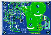
my universal (SMD or through-hole ) soldering Board.
post the schema too
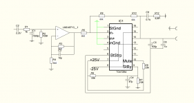
Stand-by must become "high" BEFORE Mute.
Min Gv=26Db, or ~20. Your is 17, or 24Db. That is for TDA only, buffer is not included or interested here.
1u to bootstrap is almost useles waste. This cap is power reservior, not a filter. But if you feel better with it, keep it.
Min Gv=26Db, or ~20. Your is 17, or 24Db. That is for TDA only, buffer is not included or interested here.
1u to bootstrap is almost useles waste. This cap is power reservior, not a filter. But if you feel better with it, keep it.
Last edited:
- Status
- This old topic is closed. If you want to reopen this topic, contact a moderator using the "Report Post" button.
- Home
- Amplifiers
- Chip Amps
- Optimizing TDA7294 Output