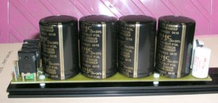
If you read the UCD thread and look for comments from Bruno he suggests a formula for calculating required size of the main caps bank. Basically he points out that "power" factors out and it depends entirely on the output resistance of the speakers.
I think the punchline was around 12,000uF per channel was good for 8 ohms? Bruno states though that he uses only small caps on his reference amp..?
I think the punchline was around 12,000uF per channel was good for 8 ohms? Bruno states though that he uses only small caps on his reference amp..?
softstart final circuit
Hi,
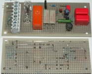
here is the final schematic of "my" softstart circuit and here the "PCB" of the softstart circuit.
Delay is about one second, recovery time (minimum time between switch off and switch on for "retriggering" the delay) below half a second.
I realised, that it is better to let all the circuit on the primary side of the supply, to avoid mixing primary and secondary voltages. The actual board is 120mmx50mm. All necessary connections to mains, two-pole mains switch and transformer are included in the connector.
Unfortunately I did not find the time to complete the amp. And I still miss the right loudspeakers for comparison of the amps too.
Regards, Timo
Hi,
here is the final schematic of "my" softstart circuit and here the "PCB" of the softstart circuit.
Delay is about one second, recovery time (minimum time between switch off and switch on for "retriggering" the delay) below half a second.
I realised, that it is better to let all the circuit on the primary side of the supply, to avoid mixing primary and secondary voltages. The actual board is 120mmx50mm. All necessary connections to mains, two-pole mains switch and transformer are included in the connector.
Unfortunately I did not find the time to complete the amp. And I still miss the right loudspeakers for comparison of the amps too.
Regards, Timo
Attachments
Read all output the intricacies of class D and especially the psu at http://www.edn.com/article/CA476906.html?nid=2431&rid=243880419
Like this:
"No matter what type of supply you use, Class D amplifiers are much more sensitive to the quality of the power supply than their linear counterparts. So, although Class D technology will almost certainly reduce power requirements by 50% or more, the actual design of the supply tends to be rather more intricate. The reason is simple: With nothing but switches (power MOSFETs turned fully on or fully off) between the supply and the output, any mains or audio-band ripple on the supply rails will modulate the output signal. In other words, all-digital Class D amplifiers have a PSRR (power-supply-rejection ratio) of 0 dB; they essentially use the supply as a voltage reference."
Jan Didden
Hi,
Not posting this to start a war!~
Howsoever:
That's brutal, but the key here is "all digital", so it doesn't really apply to the topic of this thread at all. I don't think there's very many all digital solutions out there either.
I would still agree with that, until feedback is applied in one form or another.
I guess an amplifier can no longer rightfully be considered "all digital" if it employs feedback? You would need a conversion in there someplace, which then classifies it as an analog amplifier.
ZapPulse and UcD both are not "all-digital" and do employ feedback, therefore the PSRR is not 0dB.
I have read that article, I haven't analysed it thoroughly, but it seems out of touch with what the cutting edge seems to be today (all analog, self oscillating), and perhaps, more geared towards selling their own products.
"Julian Hayes is the vice president of marketing at Wolfson Microelectronics plc "
I hope this wasn't the same article recently referenced to in our "sticky" thread here.
My views on the power supplies, I don't like the OEM way of calculating a transformer, OEM typically lacks, this is what brings us all here in the first place. I don't think DIY'rs here want to pinch pennies in areas it really makes a difference, or throw away tonnes of money in other areas where it doesn't make a difference. If we pool together we can avoid such things occuring for everyone, lessen the learning curve, and cost of it.
So I don't think 70% of calculated requirement is a good way, for whatever that's worth, I also dont' think 130% of calculated value would get you much of anything. Why not go for 100% of what the calculated requirement is, maybe 110% or 120% for good measure (usual losses etc).
Overkill here will only hurt the pocketbook.
Caps, Bruno's requirement, calculated ripple requirement, seems the smart method. He also warns about power factor .. as ewildgoose reminded us") Bruno has even provided, if I recall correctly, a very general rule of thumb for sizing them according to the load. This is engineering so there should be no black magic voodoo solution here.
Bruno has even provided, if I recall correctly, a very general rule of thumb for sizing them according to the load. This is engineering so there should be no black magic voodoo solution here.
Perhaps there are other factors to the supply capacitors which could be discussed here that might have more of an impact in quality than mere size alone. ESR.. ESL.. Ripple capability, etc.
It would be nice if we could work out what works and what is BS so we dont' all go running for split foil gimmicks that cost a fortune, and just stick to the basics that do actually work.
Kind of like, we all know what's best for rectifier diodes, right? Thanks to the dozens and dozens of previous posts on the same subject here =HexFred, or any ultra fast/soft recovery. And voila, our work is done.
Has anyone ever compared a standard set of properly selected computer grade caps to "possible" gimmicks like split foil/virtual 4 pole etc? Or do we just buy them because the marketing got to us?
Thanks,
Chris
Not posting this to start a war!~
Howsoever:
all-digital Class D amplifiers have a PSRR (power-supply-rejection ratio) of 0 dB
That's brutal, but the key here is "all digital", so it doesn't really apply to the topic of this thread at all. I don't think there's very many all digital solutions out there either.
I would still agree with that, until feedback is applied in one form or another.
I guess an amplifier can no longer rightfully be considered "all digital" if it employs feedback? You would need a conversion in there someplace, which then classifies it as an analog amplifier.
ZapPulse and UcD both are not "all-digital" and do employ feedback, therefore the PSRR is not 0dB.
I have read that article, I haven't analysed it thoroughly, but it seems out of touch with what the cutting edge seems to be today (all analog, self oscillating), and perhaps, more geared towards selling their own products.
"Julian Hayes is the vice president of marketing at Wolfson Microelectronics plc "
I hope this wasn't the same article recently referenced to in our "sticky" thread here.
My views on the power supplies, I don't like the OEM way of calculating a transformer, OEM typically lacks, this is what brings us all here in the first place. I don't think DIY'rs here want to pinch pennies in areas it really makes a difference, or throw away tonnes of money in other areas where it doesn't make a difference. If we pool together we can avoid such things occuring for everyone, lessen the learning curve, and cost of it.
So I don't think 70% of calculated requirement is a good way, for whatever that's worth, I also dont' think 130% of calculated value would get you much of anything. Why not go for 100% of what the calculated requirement is, maybe 110% or 120% for good measure (usual losses etc).
Overkill here will only hurt the pocketbook.
Caps, Bruno's requirement, calculated ripple requirement, seems the smart method. He also warns about power factor .. as ewildgoose reminded us
Bruno has even provided, if I recall correctly, a very general rule of thumb for sizing them according to the load. This is engineering so there should be no black magic voodoo solution here.Perhaps there are other factors to the supply capacitors which could be discussed here that might have more of an impact in quality than mere size alone. ESR.. ESL.. Ripple capability, etc.
It would be nice if we could work out what works and what is BS so we dont' all go running for split foil gimmicks that cost a fortune, and just stick to the basics that do actually work.
Kind of like, we all know what's best for rectifier diodes, right? Thanks to the dozens and dozens of previous posts on the same subject here =HexFred, or any ultra fast/soft recovery. And voila, our work is done.
Has anyone ever compared a standard set of properly selected computer grade caps to "possible" gimmicks like split foil/virtual 4 pole etc? Or do we just buy them because the marketing got to us?
Thanks,
Chris
I found the link interesting because it basically said that it is very important to have low ESR in your capcitorbank. Also the bank should be big enough but if ESR wasn't low this was not enough.
All ESR curves I've seen show that ESR drops with rising temperature..... Would it make sense to heat up the capacitors?
All ESR curves I've seen show that ESR drops with rising temperature..... Would it make sense to heat up the capacitors?
Hi,
So far I've really seen nothing to turn me away from good computer grade caps. They seem to have the best "package" spec wise.
Nice observation you had about ESR dropping with temp, perhaps we should look at the ESR value at operating temp.
Alot of cap manufacturers give rather sparse information on their product though, enough that you can't really compare one brand to the other alot of the time.
Well, I'll be the first to say I don't think intentionally trying to run the caps hot is a great idea, as it will drastically reduce their life span. Do you think it would be worth it? What's the rule of thumb (correct me if I'm wrong) every 10 degree C increase in temp halves the life span, over a certain range before you reach a point on either end where it of course doesn't matter (meltdown).
They aren't cheap I'd want em to last a very long time personally.
A good question to ask might be, what's a good ESR to aim for anyway? At what point does ESR no longer play a roll? No point having a cap with a lower ESR than the wires/traces themselves, at least I'd imagine anyway.
It would be great if we could just narrow the list of possibilities down to just a few brands/models that cut the mustard and leave the voodoo out of it?
For example, can anyone really say gold plated leads are worth it? We don't use gold plated wires.. I think it's pretty easy for manufacturers to stamp "audio" just so they can jack the price up, as they push their gold plated leads or split foil whatevers, and ignore the specs of it that actually do make it a decent cap for audio. Let's get some light on the subject yes?
Thanks
Chris
I know we don't want to run caps hot for the obvious reasons, but it might be a posibility to use the idea to test the effects of esr on the sound quality, while keeping the rest exactly the same.
Putting more caps in parallel operation is a much easier way to lower esr.
I also made me thinking about several famous class-A designs that use to run very hot (Old Krell's, old Musical fidelity) and had good sound. Was there a relation? Probably not but still an interesting idea.
One other thing I notice is that all theory suggest that this has most impact on lower frequency's.
My practical experience with Zap 2.2SE was that with too smal power supply the HF was much more affected. I assume that the current draw in the bass does affect the voltage on the supply rails and this generats IM distortion in treble.
Originally posted by ericpeters I also made me thinking about several famous class-A designs that use to run very hot (Old Krell's, old Musical fidelity) and had good sound. Was there a relation? Probably not but still an interesting idea.
I personally have a 50W Class A power amp (French design with bipolar transistors). The sound is very good only when it's (very) hot (15 mm).
But not sure it is the caps.
Yeah that's an idea, for testing /experimentation purposes.
Sure, this all makes alot of sense.
I wonder if ESL would play a roll on affecting the highs as well, I would think so between a certain range.
edit:
We could all really speculate until we're green in the face but someone is going to have do some serious experimentation before we get any answers, maybe they could be sent sample caps to keep costs low and help make the results meaningful, just an idea.
Hello again,
Obviously these guys are pushing products but there's alot of information here:
http://capacitors.com/portals/Information.html
Obviously these guys are pushing products but there's alot of information here:
http://capacitors.com/portals/Information.html
Hi,
I did not read the texts behind the last link, maybe there's something described better.
Thanks, Chris, for your statements to stay tuned to engineering, not to vodoo.
My opinion concerning ESR drop with temp. The disadvantage of ESR is twofold at least:
- ESR will produce heat due to the I^2*R power loss, induced by ripple current, 2A at 20mOhm will result in 0.16W. The according temp rise has to be added to the operating temp.
- ESR produces steps on the capacitor voltage (= rail voltage) due to I*ESR. This is important, because the charging current of the main caps is much higher than the average discharging current.
I did not measure it, a rough estimation instead (assuming 2A average, resulting in about 160W at 40V rails, from 10mF caps): delta(V)=I*delta(t)/C will result in 2V(!, pos and neg individually) rail drop per 10ms.
To get the charging time, I go the loop way calculating sin(x)=2V/40V; delta(t)=(90°-x)/90°*5ms (90° and 5ms are the equivalents for the raising part of the charging sine voltage).
This will result in approximately delta(t)=1ms, which ends in a charging current, ten times of the discharging one: Icharge = 20A (I(charge)/I(discharge)=t(discharge)/t(charge)). Multiplied by the ESR, this will add 0.4V steps (within 1ms) to the rails.
Hopefully I'm not completely wrong.
Regards, Timo

Hi chriscam,
Don't know myself, maybe they have that feature turned off again to save bandwidth? Your link works though.
Excerpt from http://capacitors.com/picking_capacitors/consider.htm
(C). ESR is determined by:
ESR = (Xc/Q = Xc (tan ð), with Q = 1/DF.
From this, we can see that "lossy" capacitors and those that present large amounts of Xc will be highly resistive to the signal power.
Circuit designs employing low Q capacitors usually produce large quantities of unwanted heat because tan ð and DF (or 1/Q) typically increase in a non-linear fashion with rising frequency and temperature. With some capacitors, this effect is enhanced by the naturally occurring decreased capacitance at high frequencies. High currents also produce increase heat, which in turn again increases the ESR and DF.
Even with substantial changes in current flow, high Q (low DF) capacitors will not exhibit the value shifts common to equivalent components exhibiting high DF, ESR, and other parasitics. Low ESR reduces the unwanted heating effects that degrade capacitors. This is an important goal in designing these components for high -current, high-performance applications, such as power supplies and high-current filter networks.
End of Excerpt.
Something of interest, according to this site, the affects of high frequency bypass capacitors are nullified by the wiring inductance should you put them close to the PSU's main caps. Remember Bruno saying high frequency bypass caps weren't needed, they were already on the amp? It seems this is the ideal place for them to be, since their main function is to combat the ESL.
Oh yeah, great work on the slow start circuit Timo
Regards
Bruno's capacitor sizing rule (UcD180 thread, post 441)
Bruno Putzeys said:
The amount of stored energy is a certain factor T times the amount of power (=energy per second) the amp is supposed to put out.
If the caps are recharged 100 times per second, and we want to lose (and recharge) no more than 10% of total stored energy every mains cycle (translates to 5% voltage droop), the rule of thumb becomes to store T=0.1 joules per watt (=seconds!) of rated power.
This figure in seconds also works out to be the product of load impedance and storage capacitance.
T=C*R
or
C=T/R
This is for a single rail. For dual rail systems like UcD you get two caps of half that value.
Example: For T=0.1s (rather conservative in CE terms), a half-bridge class D amplifier designed to operate into a 4ohm load requires two capacitors of
C=0.5*T/R=0.5*0.1/4=12500uF
If the fact that output power factors out is counterintuitive, consider the fact that an amp of 4 times the power will have twice the supply voltage so the same capacitance will hold 4 times the energy. Naturally, at twice the rated voltage the caps will be a bit bigger too.
Do not forget to multiply the capacitance by the number of channels connected to the power supply...
Another part of your question concerned the use of transformers.
Normally you will use one transformer per power supply. If one 2x50V supply is used to power two amps, there is only one transformer. If you have two transformers you should have two independent power supplies too (dual mono).
The only exception would be if you were to attempt making a "super-screened pair" where two transformers are stacked on top of eachother into a single steel pot and placed in parallel (but with the magnetic fields going opposite ways) with the aim of getting super-low stray field. Such an excercise is most probably overkill, given the already low stray field of good toroids.
Hope this sheds light on your question.
Re: Bruno's capacitor sizing rule (UcD180 thread, post 441)
So that's, per rail and per channel,
12500 µF for 4 ohm speakers
6250 µF for 8 ohm speakers
Timo, to pick up from your last post (#320) in the UcD400 thread, apart from overkill and inrush current, oversizing the capacitors increases the peak recharging current, which may not be totally innocuous even if it doesn't increase the corresponding voltage pulse due to ESR (if you double the capacitor you double the peak current but you halve the ESR so R*I doesn't change)
stef1777 said:Hi Folks!
I tested my UcD180 mono block with and without the filtered IEC plug. No difference.
What is the common symptom with this when problems with the filtered IEC plug?
Stef...
So that we have a copy in this thread for future reference, here is Bruno's opinion (post #345 in UcD180 thread):
-------------------------
Do not use mains filters with Y capacitors installed. An Y capacitor makes a capacitive connection (several nf) from the mains lines to your chassis and hence audio ground.
So there is the audiophile designer, using transformers with a shield to remove the slightest chance of the mains polluting his system ground, then installing a schaffner inlet that puts 2.2nF straight from the mains into the chassis, simply because he heard somewhere that mains disturbances are audible. They are, more precisely when such a filter is used.
All commercially available "combined mains filters" have Y capacitors. Don't use them. If all your audio devices are connected to one wall outlet (likely), you can use such a filter there, but by no means on individual boxes.
In principle you could make a filter with only chokes (cm/dm) and an X capacitor. Fine with me, but unless you have a problem with heavily polluted mains you don't need them. The UcD will not be a source of mains pollution. If your mains are polluted by an external cause (like you have a car factory next door), a centralised filter on the outlet is more effective.
Fyi, none of my audio devices have mains filters on them.
----------------------------------
Stef, Bruno's arguments do seem to make sense. To actually hear the difference you could try testing again while deliberately creating mains disturbances eg by having somebody action a power drill somewhere in the house. Do keep us updated
- Status
- This old topic is closed. If you want to reopen this topic, contact a moderator using the "Report Post" button.
- Home
- Amplifiers
- Class D
- Optimal supply design for UCD and Zappulse modules