Also, there was a really good driver design worked out by Tubelab_com, in a thread called "Class AB2 Amp" in which member chrish builds a triode-wired push-pull 6L6GC amp using a driver that uses two 6SN7 (or 6N8S). The first stage is an LTP phase splitter, the second stage is a differential driver which is followed by a pair of MOSFET source followers to drive the snot out of the 6L6GC grids. That should work great for GU-50 tubes too.
6L6GC AB2 Amp
-
6L6GC AB2 Amp
-
If you are interested, attached are schematics of my GU50 experiments. I got 75 W.
That's impressive. What kind of OPT did you use? How much GNFB does it use and what kind of distortion numbers did you get?
The output transformer was this:
TGL 40/001 INDEL - Transformer: speaker | 40VA; Sec.winding imped: 8Ω; 0.04/16kHz; TGL40/001 | TME - Electronic components
Is has only 40 W output power specs, but it has been built around 180 VA core, it works fine up to 100 W.
That project is from 2014 and I don't find my documents, just these notes:
In an other forum I have written:
I made PCB's for the power supply and driver board. I remember that some Finnish DIYers built these amplifiers.
TGL 40/001 INDEL - Transformer: speaker | 40VA; Sec.winding imped: 8Ω; 0.04/16kHz; TGL40/001 | TME - Electronic components
Is has only 40 W output power specs, but it has been built around 180 VA core, it works fine up to 100 W.
That project is from 2014 and I don't find my documents, just these notes:
- Test conditions: +Ub = 480 V, Ug2 = 350 V, Ug1 = -55 V, Ik (idle) = 50 mA/tube, Rload = 4k
- Pout = 24,5 V @ 8 ohms---> 75 W max.
- Ug2 had to be raised to 350 V to get sufficient power from quite low impedance OPT (4k)
- Optimum conditions would be + Ub = 500...550 V and Rload = 6k to 8k.
In an other forum I have written:
...GNFB 12...14 dB... THD at 50 W is 0.2...0.4%.
I made PCB's for the power supply and driver board. I remember that some Finnish DIYers built these amplifiers.
The output transformer was this:
TGL 40/001 INDEL - Transformer: speaker | 40VA; Sec.winding imped: 8Ω; 0.04/16kHz; TGL40/001 | TME - Electronic components
Is has only 40 W output power specs, but it has been built around 180 VA core, it works fine up to 100 W.
That project is from 2014 and I don't find my documents, just these notes:
In an other forum I have written:
I made PCB's for the power supply and driver board. I remember that some Finnish DIYers built these amplifiers.
Hello.
Polish watts are not the same as Chinese watts:
My iron measures 86 * 72 * 50.
Yours is 102 wide.
However, it is also the diameter of the wire which sets the maximum current.
a larger width allows a thicker thread.
Look:OPT PP for GU50 Triode ?
He use 0,35mm copper wire to build his own transformer.
Last edited:
Hello Artosalo,I made a simulation too (again).
I got 24 W with 3.9 % THD (mostly 3rd.) with 8 ohms (3k5 p to p) and
17 W with 3.2 % THD with 16 ohms speaker (7k p to p).
I have a question about your schematic,please:
Why do you add a 1 Ohm resistor at the anode ?(R8 and R10).
OPT PP for GU50 Triode ?
Regards
Last edited:
Ah, I think I just understood something. If you allow 3+% THD of course you can get 20+ watts out of a pair of GU-50 in triode. I stop quoting power output beyond 1% THD, so in the simulations I've done with PP GU-50 in triode with 400V Vak I get about 13 to 15 watts maximum. That's the same thing, just with different measurement limitations.
So yes, PP GU-50 in triode will get you about the same power as PP 300B, and with similar drive requirements.
One major difference is that the internal resistance (ra) of a triode-wired GU-50 is higher than that of a 300B, so the GU-50 triode will work better into a higher impedance primary, while 300B works better into a lower impedance primary. Typically you'll see PP 300B running into a 3.5k or 5k ohm primary (anode-anode). GU-50 works better into OPTs designed for 6L6-triode or similar, with 6.6k or 8k ohm primary (anode-anode). If you can find a high-power 10k:voice coil OPT then that would be even better for GU-50 triode.
Fortunately, triodes are tolerant of some impedance mismatching. A lower than optimal load impedance gives you a bit more power, but at higher distortion and reduced damping of the loudspeaker load. That means you'll have to apply negative feedback to get 'hi-fi' results. You'll also need to apply more negative grid bias to keep the tube from drawing more anode current than desired.
But yes, you can certainly make it work.
I've read many places, and here too, that GU-50 works best in pentode, with a high anode voltage (500V or so) and the g2 voltage kept at 300V or lower, preferably from a regulated voltage supply (the anode voltage does not need to be regulated). But that's a whole other kettle of fish...
--
Attachments
Hello Rongon !
Thanks a lot !
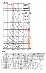
I'm begining to understand push-pull load line :The Valve wizard had help me and the triode calculator too:
Universal loadline calculator for vacuum tubes - Vacuum Tube Amplifiers - DIY
OPt seems to be around 65 ma vg near -70v...
But for the moment i'm studing ccs for drivers with a pnp transistor
Thanks a lot !
I'm begining to understand push-pull load line :The Valve wizard had help me and the triode calculator too:
Universal loadline calculator for vacuum tubes - Vacuum Tube Amplifiers - DIY
OPt seems to be around 65 ma vg near -70v...
But for the moment i'm studing ccs for drivers with a pnp transistor
Thanks for the link to the online loadline calculator. I hadn't seen that before. Nice find.
When you load your GU-50 into that calculator, set it SE and to Triode (of course), but set the Load (Ohm) to *half* the Ra-a of your OPT, so for a 3.5k:VC OPT set that to 1750 (ohms). Then set the anode voltage to 400V, the quiescent current to 70mA.
That matches the easy way to draw a loadline for push-pull operation. You do it as if you were making a loadline for single-ended operation, but at half the load impedance (or resistance).
So... With those parameters entered, do you see the operating point? It's way over to the right, with not much room to swing along the loadline to cutoff (0mA anode current). All the room on the loadline is to the left, towards 0V on the grid (grid current region). That means your output stage will be spending a lot of time running in class AB, with one GU-50 going into cutoff when the output stage is driven harder (higher input voltage applied). That will create a crossover notch at higher outputs while one of the GU-50 tubes is not drawing much current and the other one is. You will need to use negative feedback to smooth that out.
Now try the same operating points, but this time with a 300B.
It too is pretty far to the right on its loadline, but not quite so much as with the GU-50 triode.
Also, you can see that as you go farther right on the anode curves, the 300B anode traces stay more upright, while the GU-50-triode traces start to 'lay down' to the right (they get flatter, less upright). That means the 300B stays more linear as it approaches cutoff.
All this argues for using the GU-50 with a higher impedance load, so that it can operate more of the time in class A, farther away from cutoff (closer to 'centre-biased' for more symmetrical swing).
I tried it with 3300 ohms to simulate a 6.6k ohm OPT like one would typically use for PP 6L6GC. Try lower anode voltage too, let's say 350V. Set the anode current to 90mA. See what happens? Much lower THD, but less power out.
Now set the quiescent current lower, let's say to 75mA. That's a good looking spot too. My takeaway? GU-50 works better into higher primary impedance, like 6.6k ohms, or even 10k ohms. But it will work into lower primary impedance like 3.5k ohms, sure. The tube will act differently, though, and you'll want to design for that situation.
--
Push-pull
Read this please.
Двухтактный ламповый усилитель для <<тяжелых>> колонок на ГУ-50 | Техника и Программы
Read this please.
Двухтактный ламповый усилитель для <<тяжелых>> колонок на ГУ-50 | Техника и Программы
For the OPT, it says,
Is that a turns ratio of 2400:120 ?
If so, that would be a 20:1 turns ratio, so yes, about 3.2k:8 ohms.
However, there is an elaborate feedback circuit in place in that design. I don't know how that particular feedback circuit would interact with a different OPT than what the author used. But heck, go for it!
Personally, I'd design for lowest THD possible first, then add negative feedback as needed to get the most pleasing end result.
--
Also, that 6N1P as the active load in the tail of the LTP could be better. Probably better done with a depletion mode MOSFET like DN2540 or 10M45S. Cheaper and easier than a 6N1P too.")
Output trance parameters.
iron from TS170
Primary - 2400 turns of PEV-2 0.35 mm. Three sections of 5 + 10 + 5 layers,
120 turns in each layer. R act - 108 ohm.
Secondary with the same wire 120 turns, a tap for 4 ohms from the 85th turn.
Two sections with four parallel layers. There are eight parallel layers in total.
R act of the secondary - 0.7 ohm. The given is 280 ohms.
The efficiency is 89%.
Is that a turns ratio of 2400:120 ?
If so, that would be a 20:1 turns ratio, so yes, about 3.2k:8 ohms.
However, there is an elaborate feedback circuit in place in that design. I don't know how that particular feedback circuit would interact with a different OPT than what the author used. But heck, go for it!
Personally, I'd design for lowest THD possible first, then add negative feedback as needed to get the most pleasing end result.
--
Also, that 6N1P as the active load in the tail of the LTP could be better. Probably better done with a depletion mode MOSFET like DN2540 or 10M45S. Cheaper and easier than a 6N1P too.
Last edited:
+1 on that.
And... If you're going to have poor damping factor -- which requires the application of negative feedback -- why go for triode output tubes that give you only low power? You might as well go pentode and get all the power GU-50 tubes are capable of.
Wavebourn (Anatoliy) has done extensive work with GU-50 tubes. When he suggests using them in pentode with high anode voltage, low screen voltage and a 10k OPT, I'd listen to him. He also has written that GU-50 is not the greatest in triode.
I have some GU-50s, but if I was to make a PP amp with those in triode, I think I'd use them with at least a 6.6k OPT (8k or 10k would be better) and Va of only about 350V, Ia of maybe 90mA per tube. Similar to 300B operating points but with a higher value of load impedance. Maybe they'd sound good without negative feedback that way, or maybe they'd sound good with only a little bit (6dB or so).
But that's just my opinion. As they say... Your mileage may vary.
--
And what's this about 6N7S driver? Do you mean 6SN7? The schematic shows 6N6P. That's a lower ra, higher gm triode than 6SN7 (6N8S). I'm confused...
--
Last edited:
- Home
- Amplifiers
- Tubes / Valves
- OPT PP for GU50 Triode ?