Двухтактный ламповый усилитель для <<тяжелых>> колонок на ГУ-50 | Техника и Программы
2400 turns and 120 turns do 3,2kΩ 8Ω . Voltage is 400v
2400 turns and 120 turns do 3,2kΩ 8Ω . Voltage is 400v
Yes more than 68vp .In class AB₁ I get 16W with 8%, are you driving in class AB₂ with input swing over 68vp?
In class AB₁ I get 16W with 8%, are you driving in class AB₂ with input swing over 68vp?
I noticed at post #18 that you have -108 Vdc as bias voltage ??
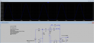
My results are at class A. Attached the plate current of one GU50 at full drive.
As you see the plate current do not drop below some 60 mA.
The drive voltage at g1 is 68 Vpp. DC-bias at g1 = -68 V.
Attachments
Last edited:
...are you driving in class AB₂ with input swing over 68vp?
And as you see from post #16, my simulation circuit is ordinary RC-coupled (at the g1).
Such circuit can not be driven into grid 1 current, i.e. into class AB2.
Kokoriantz,wich software are youusing please ?
Tina ti free from texas instr.
I read on your schematic 97+7=104mA.
Is it the maximum value?
If yes what is the lowest ?
And working point ?
I have no lt spice and don't understand the push-pull load line
104 mA is plate current + screen grid current (=cathode current) at idle (no signal condition).
Look at my post #24. There is the plot of plate current.
The max. value of the cathode current at full drive is 310 mA and min. 65 mA.
Working point ?? It is the idle condition.
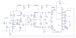
Look at the schematic: Ua/Ug2 = 428 V, Ik = 104 mA, Ug1 = -68 V.
For the rest i will use 6n8s for drivers and Schmitt phase spliter(long tail pair ?).
Do you have the schematic yet ?
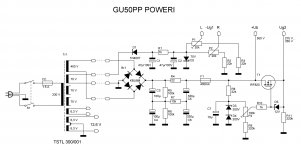
If you are interested, attached are schematics of my GU50 experiments. I got 75 W.
Attachments
Maximum current for this transformer is 170ma even it is a 50w transformer104 mA is plate current + screen grid current (=cathode current) at idle (no signal condition).
Look at my post #24. There is the plot of plate current.
The max. value of the cathode current at full drive is 310 mA and min. 65 mA.
Working point ?? It is the idle condition.
Look at the schematic: Ua/Ug2 = 428 V, Ik = 104 mA, Ug1 = -68 V.
That kind from you.I save them.Do you have the schematic yet ?
If you are interested, attached are schematics of my GU50 experiments. I got 75 W.
I have my schematics,i will use 6n8s for drivers and Schmitt phase spliter.
Maximum current for this transformer is 170ma even it is a 50w transformer
So what ??
That does NOT mean you can not have 104 mA / tube idle current. That 170 mA is some sort of recommendation. Can you show the data sheet of your output transformer ?
What manufacturer / type ?
Ra is 3,5k even it is 0,875k Ia is lower than 40ma ?!
Sorry I don't understand that question ?
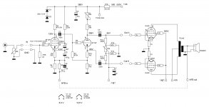
Here's a schematic of an idea using PP GU-50 in triode and two 6N8S (= 6SN7).
The B+ is 400V and it uses fixed bias for the PP GU-50 pair.
The simulation predicts very low distortion and about 17 watts max power out to the speaker.
It's a 'Williamson' driver circuit.
The 4.7k ohm global feedback resistor is just an approximation to get about 6dB NFB.
It's just an idea. But it looks pretty good in theory.
PS - The output transformer model used is for a Dyna A470, which has an approx. 5k primary impedance.
Attachments
Last edited:
The concertina doesn't swing that many volts. It's followed by a differential pair that swings lots of volts.
All the concertina does is split phase. That way the differential pair does not split phase, so that stage can be a more effective driver. The differential pair receives a balanced input, after the phase splitter.
One of the problems with using a long-tail pair (LTP) as a combined phase splitter and driver is that it has both those jobs to do.
I think what you're looking to use is commonly called a 'Mullard driver', named after the Mullard 5-20 amplifier. That will work, and will be more stable with negative feedback applied since it has fewer low frequency pole points in the signal path. However, it will be less linear, so you'll be tempted to apply more negative feedback, which might cause instability.
Everything is a compromise between this and that. Nothing is perfect.
--
- Home
- Amplifiers
- Tubes / Valves
- OPT PP for GU50 Triode ?