There was discussions here about the headphone out of the 105/105D models. Also many critics about Oppo`s way of configuring the DAC outputs, allocating two of its channels to the headphone output. This configuration is impossible to modify it, and so the two DAC channels are almost lost, if the user is not interested in the headphone option...
Well, if is nothing to be done with this Oppo design, and the DAC channels allocation, then the only one can do, is just using it...
There is a quite big quality potential in this headphone section: two of the DAC channels tied together, as less components in the signal path (only the I/V stage, the excellent headphone amp chip, TPA1620, and less filters involved in th e signal path, than in the RCA/XLR stages). The TPA1620 is an current feedback amplifier, and therefore it provide very good quality performances as an final buffer: very low noise, good dynamics and a huge slew rate.
Recently, I improved this headphone output for someone who it use it frequently, in addition to the general improving of an 105D model. As I do not own a top model headphone to test this improved stage, I decided to test it as a line out. The surprise it was very big indeed, as I did not expect a so high quality from this stage.
The conclusion is: if this stage as the rest of the 105/105D model is improved accordingly, then the headphone output it can be used either with good headphone, or pur and simple, just as a supplementary line out, directly connected to an power amp (also a digital volume controlled output). Very impressive performances!
I decided already to implement the TPA1620 chip into my output module (new version) together with OPA1632...
Last edited:
I just tried it Coris,I agree.
In fact I will finish the digital side first.As an experiment I pulled out the three 1000uf caps on the input of the AP1122 and LDO1117.
The soundstage shrunk and it sounded rather bad.I popped a 4700uf back in on the 3.3v regulator input and it returned to its original sound.
I am trying to find out which 1.2v regulator runs the ESS9018 core and which runs the ESS9018 analogue channels.
I have 3 x 6800uf on the way for the input caps and a 18,000uf for the main rectifier cap although I am unsure how good Wurth caps are.
I will then remove the 1000uf caps after the regulator to see how it sounds but I understand they need some capacitance on their output to prevent oscillation.
Then I will look at the headphone section.I ma listening to it now and am very impressed.Feels like a layer of grunge has been removed.Very open and transparent
John
Hi Coris
Have tried headphone output.Def better but seems to have some hum on it.
9mv dc offset on one side and -0.4mv the other.Will try a better cable.
Also can you confirm the voltage going through the 5v out on the SMPS is 5.18v approx going through both the 220uf caps and the 220ufs following the inductors?
That way I could use 10v or 6.3v caps in it
Many thanks
John
Indeed, there is a hum on headphone out on an original (un improved) device. This is because the enough high ripple on the power system on stereo board. Massive filtering it will get rid of this hum...
9 mV offset is quite much. The offset it may differ from chip to chip. I found 6mV and 0 on other channel.
The voltage out of SMPS it should be 5,2v. This is because the USB voltage it have to be 5v... Well, it not matter so much this 0,2v over 5v...
You may know that increasing the filtering capacity on the SMPS outputs, it not lower the HF noise level. There is not recommended too high filtering capacity there, as it may engage the protection circuit on power up, and the SMPS it may not deliver power at all. Also the voltage rating for these caps it should not too low. It is better to use 25v rating caps in this place (for 5v rail), and however, lowest ESR/ESI as possible components...
Best of all, use a linear PSU instead of that SMPS...")
9 mV offset is quite much. The offset it may differ from chip to chip. I found 6mV and 0 on other channel.
The voltage out of SMPS it should be 5,2v. This is because the USB voltage it have to be 5v... Well, it not matter so much this 0,2v over 5v...
You may know that increasing the filtering capacity on the SMPS outputs, it not lower the HF noise level. There is not recommended too high filtering capacity there, as it may engage the protection circuit on power up, and the SMPS it may not deliver power at all. Also the voltage rating for these caps it should not too low. It is better to use 25v rating caps in this place (for 5v rail), and however, lowest ESR/ESI as possible components...
Best of all, use a linear PSU instead of that SMPS...
Last edited:
Thank you Coris
Having popped the board back in the hum seems to have gone so maybe the plug in cable was not right in before.
Also noticed headphone output seems higher compared to balanced output.
Have popped 6800uf before the 3.3v regulator.Much improved detail and soundstage.6800uf on U1 (1.2v ESS 9018 core voltage)made no difference to sound.
Will next do U23(ESS 1.2v analogue voltage)
I do enjoy working on the 105D.May increase decoupling on the TPA 6120
Thank you for advice.Sounds best to leave the SMPS alone
John
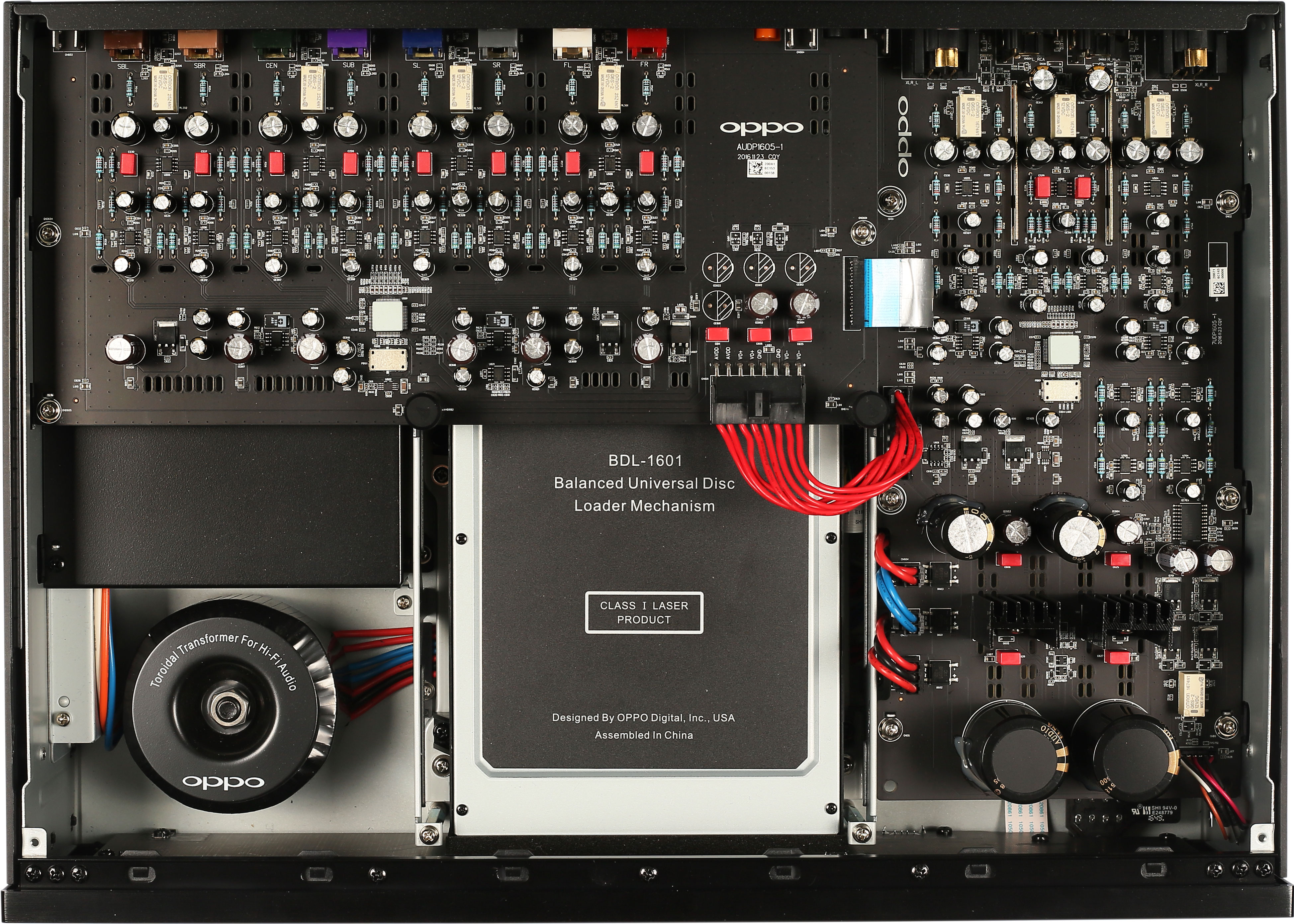
Looks like separate clocks for Stereo and Multi-channel. Rectangular with four black corner dots - that has to be the oscillators. If so, not a bad thing and gets rid of that Texas chip sending a balanced clock signal up to the M-CH via the ribbon.
Go to Oppo's website for full resolution hit "+" on the photo. If they were just slightly more detailed, we could see legends with part numbers, like R530 and C40 etc. It's almost there, but falls just short.
Go to Oppo's website for full resolution hit "+" on the photo. If they were just slightly more detailed, we could see legends with part numbers, like R530 and C40 etc. It's almost there, but falls just short.
Last edited:
Hello.
Anyone know if this product looks to work good ?
Its realy cheap....
https://fr.aliexpress.com/item/ZERO...lgo_pvid=cd633b48-00be-41bf-b5ca-ed213535511b
They have linear for OPPO103 and 203.
https://fr.aliexpress.com/item/ZERO...lgo_pvid=cd633b48-00be-41bf-b5ca-ed213535511b
https://fr.aliexpress.com/item/Spec...lgo_pvid=48d1c373-a8db-48cb-8873-c570a352a06e
What/who is Zerozone
UPS!!! We should continue the discussion into the dedicated thread for 203/203 devices...
http://www.diyaudio.com/forums/digi...205-discussions-upgrades-modifications-8.html
http://www.diyaudio.com/forums/digi...205-discussions-upgrades-modifications-8.html
Hi Coris
On the basis that I have raised the analogue power supply and digital power supply capacitance far higher
(analogue orig 6800uf x 2 now 22,000uf,Main digital was 3300uf now 18,000uf.Pre reg caps 1000uf now 6800uf)
Would it be possible to reduce the local de coupling capacitance on the ESS9108?
At present they are 220uf but I have some 100uf 6.3v Black gate Ns I would like to try.
Thank you for any info.
John
Hi Coris
On the basis that I have raised the analogue power supply and digital power supply capacitance far higher
(analogue orig 6800uf x 2 now 22,000uf,Main digital was 3300uf now 18,000uf.Pre reg caps 1000uf now 6800uf)
Would it be possible to reduce the local de coupling capacitance on the ESS9108?
At present they are 220uf but I have some 100uf 6.3v Black gate Ns I would like to try.
Thank you for any info.
John
Hi John
Well, nothing it have to be reduced, but increased... It is no any benefit from replacing the 220µ with 100µ... The voltage rating is OK, but the value it should be higher... If you do not have enough place to mount the caps on the upper side of the board, then you can do it on the downside. There is plenty space there....
Only using the HC4040 as single stage, from 50MHz to 25MHz (Oppo 95) and 54MHz to 27MHz (Oppo 105). The 74LVC161 form factor is 48 pin SMD and the non-SMD HC4040 so easy to use.
The "SAW" advantage is easily coming through the HC4040, and are both powered by the Terra Firma 3.3V - and it adds only a modest amount of added current. The point of TF is that it makes for a much more analog sound as it target sub-1 Hertz noise/jitter via power supply (it supposes than Alan Deviation is audible - some find that hard to believe). That advantage must come through the divider and it most certainly sounds that way.
Any added propagation delay may not be ideal here. The effect it may have on the TF is a worry.
So until something better comes along...?
The only advantage to using a saw over a square wave clock is lack of noise generated by square wave rising edge. It much easier to clock a square with a high degree of accuracy.
The most important of the clock it intrinsic jitter, in the oscillator. All fiber optics gear is clock on a square, network system or clocked on a square. However communities networks try to run stratum one clocks.
Cheers
Cheers, Joe
I do not want discourage (give up) eganz1, but I will express my point of view regarding the switching PSU in Oppo player, and in general in a digital system.
Feeding a digital system with linear power is only positive, thinking the quality of the approach. But when a digital system use quite much current, the efficiency of a serial PSU degrade much in such case. The big cons of a serial PSU is its heat dissipation for important currents.
On the top of this cons it come another one, which it negate the benefits of a cleaner serial PSU. A digital system is noisy by its way to work. This is a very solid fact! The only way to reduce the digital system noises is filtering, and shielding the eventual EMI noise generators. So, using a serial PSU, one feed the system with a clean power for a very noisy device/load. Benefit/result = 0 (nonsense). More, one get quite much heat from the working serial PSU...
What is to be done (more reasonable)? Minimise the noise generated by the switching PSU itself. Long connection wires between the PSU and the targeted circuits, is just bad. This is the case of Oppo players. Long connection wires act as good emission antenna for the HF noises of the SMPU. Solution: better power rails decoupling, shielding of sensitive circuits, better filtering out the HF noises.
In the Oppo player case, the SMPU is meant to power the mother board of the player, and the CD/BR transport (which it need quite important currents). The analogue stage (lower current hungry) it use already a separate serial PSU. This approach of the design is very reasonable. So it have to be.
In my opinion, the only improvement one it may bring to the digital stage, powered by a SMPU, is to specially care of powering the oscillators with a very good (low noise) local PSUs. This exclusively clocks dedicated PSUs it may be a serial regulator, shunt regulator, battery. The impact of cleaner power for the system clocks is quite high for both audio and video stages of the player.
I still think that the SMPU in Oppo is in the right place. Only some corrections it may be done to lower the SMPU EMI noises, even more. For production reasons, Oppo did not paid attention to such details...
Else, I think Oppo Company should react when somebody use its marketing name, to promote another or himself products... Or OPPOMOD it may have the right permission from the Oppo Co.? Anyway, this is another story and not our business...
You're out in left field on this, low noise does not equal SMPS. These are designed for computers where low noise is not critical. It's a proven that linear supplies out perform SMPS in every area except for effientcy and since when are audio files worried about burning extra power.
- Home
- Source & Line
- Digital Source
- Oppo's BDP105 - discussions, upgrading, mods...