There is indeed, a benefit in replacing the original resonators (20/27Mhz) with oscillators. Oscillators (some good ones) are more precise components, and it can provide better parameters for the clock signal, than the internal integrated PLL, driven by a external resonator, it can do.
The advantage in using resonators, is the simplified power system, as these devices does not need to be powered. Else, using oscillators, one should provide power to it.
Now is the question where to take that power from. The immediate accessible power for such oscillators are the existent power rails on board (3,3v or 5v). There are used DC/DC converters to create the 3,3v rail. Or one can use the 5v rail which it come from the main PSU, and then regulated down to 3,3v. To keep the good parameters an oscillator it have, one should power it from a high quality PSU. There is the DC/DC converter a such quality PSU? Definitely no.
Else, no matter how good the main power supply it may be, the power rails on the digital board are strongly perturbed by the usual noises generated by the digital process.
So, in my opinion the solution here is to use a independent PSU, dedicated exclusively to these sensitive devices: oscillators. As known, my approach is to use battery power for such devices...
To conclude (answering your question):
There is a benefit to replace the 20/27Mhz original clocks - YES.
There is a benefit to not use, or doing this replacement without external PSU - NO. Actually there is not possible without a whatsoever external power solution, when using oscillators...
Last edited:
There is indeed, a benefit in replacing the original resonators (20/27Mhz) with oscillators. Oscillators (some good ones) are more precise components, and it can provide better parameters for the clock signal, than the internal integrated PLL, driven by a external resonator, it can do.
The advantage in using resonators, is the simplified power system, as these devices does not need to be powered. Else, using oscillators, one should provide power to it.
Now is the question where to take that power from. The immediate accessible power for such oscillators are the existent power rails on board (3,3v or 5v). There are used DC/DC converters to create the 3,3v rail. Or one can use the 5v rail which it come from the main PSU, and then regulated down to 3,3v. To keep the good parameters an oscillator it have, one should power it from a high quality PSU. There is the DC/DC converter a such quality PSU? Definitely no.
Else, no matter how good the main power supply it may be, the power rails on the digital board are strongly perturbed by the usual noises generated by the digital process.
So, in my opinion the solution here is to use a independent PSU, dedicated exclusively to these sensitive devices: oscillators. As known, my approach is to use battery power for such devices...
To conclude (answering your question):
There is a benefit to replace the 20/27Mhz original clocks - YES.
There is a benefit to not use, or doing this replacement without external PSU - NO. Actually there is not possible without a whatsoever external power solution, when using oscillators...
Ah, okay. Got it. Thank you. I didn't realize the on board clocks were resonators/crystals without power. Luckily I have two small TPS7A4700 3.3v and 5v power supplies I can use. Maybe I can remove the audio board and fit them there (I'd like to get your clock upgrade but probably can't until next year).
Any particular clocks you recommend? Crystek, Abracon, etc?
Digital volume it control both XLR/RCA outputs for stereo...
Thanks Coris
Will try the XLR outputs soon to compare them to the RCA outputs
John
Ah, okay. Got it. Thank you. I didn't realize the on board clocks were resonators/crystals without power. Luckily I have two small TPS7A4700 3.3v and 5v power supplies I can use. Maybe I can remove the audio board and fit them there (I'd like to get your clock upgrade but probably can't until next year).
Any particular clocks you recommend? Crystek, Abracon, etc?
Crystek, Abracon are all right, of course... ADM7151 it could be by far a better choice to power oscillators...
You can try, but honestly, I appreciate as a much better idea about waiting until next year, than making improvisation with "small TPS7A4700" and "5v power supplies", when about clock signals...
")
Thanks Coris
Will try the XLR outputs soon to compare them to the RCA outputs
John
XLR is better. However, best is to use that digital volume set it to "fixed volume", and then adjust from amplifier/preamp...
Thank you CorisXLR is better. However, best is to use that digital volume set it to "fixed volume", and then adjust from amplifier/preamp...
I have a Tisbury Mini passive amplifier.But removing it and using the digital volume was an improvement.Even on cheap interconnect.
The amp is a Musical Fidelity F16 power amp.Then down into Kimber 8VS leads into PSB VS400 speakers.The detail improved and the soundstage widened and became deeper.
So I have 3 metres x 2 of Kimber psb on the way to try it on the XLR outputs as the F16 as balanced XLR inputs
Ta for the help Coris
Another well working clocking approach for 105D: master SAW oscillator 108Mhz, which will directly clock the DAC chip. Then this frequency divided to 54Mhz for Darbeee chip, Finally the the 54Mhz frequency divided to 27Mhz for main processor and HDMI chip. This whole circuit powered by battery.
There is of course a delay in such cascaded dividing, and so the Darbee chip and the main processor/HDMI chip do not get a perfect synchronised clock signal. I appreciate a such issue as low important for the whole system, as the internal stages inside the receiver chips may however fix this few ns delays. At least there is always only about the same delay, and there is a much better situation so, than each chip heaving its own clock signal, which it have to be aligned with the rest of the system clocks for variable and random delays.
In this clocking approach, the best quality clock signal it goes to the DAC chip, and I appreciate this as big advantage.
Last edited:
Well, a such component replacing is not just a risk free operation... At least, replacing the original resonator with a oscillator, it involve some other changes on the PCB clock area, as some other risks, if a such modification is not well prepared, all points of view...
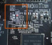
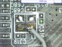
I will use the opportunity here, to remind to others who may proceed to this mod, that the easiest way to remove the original resonator, is to put the soldering iron right on the resonator (it will be of course destroyed, but who cares...), wait until the solder it melt under it, and then remove it at once from the place on a side (in same plane with the board), but not lifting it right up. The copper pads on this type of PCB are very fragile, and very easy to disclose it. The PCB is not meant for rework purposes...
Together with the old resonator, one should also remove the caps and resistor around it, as seen on the picture here. The two clock traces going into the chip, should not have any component connected to it, before injecting the clock signal from a oscillator, in one of that traces.
For safety and more protection for the HDMI chip, I will suggest to AC couple the oscillator to the clock input pin of the chip. This it mean to inject the clock signal through a (SMD) cap, and separate the eventual DC level of the oscillator output, from the clock input pin of the chip. So, only the clock frequency it will goes into the chip.
When the mod is done so as you did, it is quite difficult to introduce a so small cap in between, in the signal path. However, such protection is strongly recommended, as one do not know the details about how tolerant this clock input it may be. Mainly this input pin is meant and designed to have a resonator on it...
I assume the picture here is clear enough to well show the PCB details. The clock area should look like in the picture, before installing the new oscillator in place, or connecting the coax for clock signal.
Attachments
Last edited:
Thanks Coris. I was able to remove the clock without issue with a hot air gun. I pulled the tab using wire that was a little too thick. I was tired and should have stopped working for the night. Oh well.
Hm AC coupling. smd would be tricky but i may have some 100pf wima film caps...
Hm AC coupling. smd would be tricky but i may have some 100pf wima film caps...
I assume your idea is (or it was) to solder somehow the oscillator on the board, using the old resonator`s useful pads. This it could be a good idea, but in your case, doing this only once, and not knowing for sure how it will works finally, I will suggest you to solder somehow the oscillator in a vertical position (on its longer side) on one of the GND pads available. This it may not be a just right position for the component, but it will give the possibility to experiment, and/or it will allow a make easier the rest of the connections around. A very short and very thin solid wire from oscillator`s output to the clk input of the chip, it may be one needed connection. Then a wire from the Vcc tab of the oscillator to its power device, it may be the second one. This wire should be quite flexible, thin and it must be well glued on the board very near to the "construction". It is also better to insert a (at least 1k) ferrite bead on the Vcc line of the oscillator, right on the connection point to the oscillator. You may not forget a necessary (also very small cap) between Vcc pad and GND pad of the oscillator (right on the pads).
I will suggest to introduce a small SMD cap (ceramic 1n) in between the oscillator output and the clk chip input point. Definitely it should not be used byger components here (cap or ferrite bead), but the smallest possible for you to manage with, and solder it.
If after all is finished successfully, and no picture on the screen, then do not despair. The output level of your oscillator it may not match with the input level for the clk pin of the chip... If such (unhappy) moment occur, then you should try to find the right clock signal level to make the chip to work as it should. In such case you should have some measurement devices to know quite precisely what about you may have there, appreciating how to adjust it for best fit...
Let`s hope it may not be actual a such scenario, in your case...
Last edited:
I would like to repeat my advise against using hot air guns to remove components on these type PCB Oppo it use for their devices, and similar.
I appreciate as very risky this hot air procedure. I experienced also myself how dangerous it can be to use a such thing.
First I will mention the enough low control one may have in using a such hot air device, over the working area. This tool it warm up at high temperature a quite large area on that PCB (also in its depth), and around the targeted point, even though one may use devices to focus that hot air. Today components are extremely small, and the air pressure of a such device it can blow away at once a very small cap or resistor from its place in the neighbour of the working area. Just imagine what it could be the adjacent result of using a hot air gun, when a whatsoever passive component it is removed from its place, and you do miss that exactly moment when it happen. You will never know what it was removed, and where it flew that component. It could be attached to another one, or it could be freely inside the device you are working on... And then start up the device, and wonder about one or another... Imagine if the hot air gun it accidentally blow away at once, two very small components from its places around the working area. You will never know which component it were disclosed from, if you are lucky enough to see where the components disclosed are...
I will strongly advice to not use such hot air tool for removing components on these modern PCBs, or mobile phones, except special measures are taken to protect the surrounded areas of the working point.
Much more safe and accurate procedure is to use the soldering iron, with an enough large melted drop on it to remove a quite small component from a PCB. Even a larger component as a processor or another kind of chip it can be removed by (carefully) cutting its legs with a knife or another tool, and then remove the rest of the pins from the board using a soldering iron.
Last edited:
Well despite my poor wiring and soldering, both new clocks seem to be running okay. The effect on video performance is interesting. I am using Crystek C3391 20mhz clock. I am not sure if it's better or not. I see more 'noise' or grain in Blu-ray and the streaming Netflix I see what appears to be more noticeable compression. On the good side, there is greater resolution and color fidelity is richer with more depth. My guess is the new clock makes the Oppo *very* revealing image quality. So much so, that I realized that HDMI 1 image looks very different from HDMI 2. So I searched google and found out that output 1 uses the Marvell processor, but output 2 is 'pure' or 'direct' image! I now prefer output 2 as it seems more accurate. HDMI 1 is perhaps *too* revealing.
For music, I am using Fox Xpresso for 27mhz clock. And it sounds terrific! Sound quality is almost liquid, 'musical', almost too much so. Very interesting. Reminds me of TDA NOS DACs. So I wonder if changing the clock has allowed my soekris to reveal its true qualities? In any case, I absolutely think the clock upgrade is mandatory for the coaxial output to DAC.
I know my implementation isn't very good, so I'm sure Coris that you're upgrade must sound amazing. I will have to be patient though until next year.
EDIT: I notice the black color depth in video playback is incredible. I use a BenQ W1070 for movies and it supposedly has 'so-so' black performance. Not anymore! Perhaps projector reviewers need to mod their players!
Last edited:
Well, well, congratulations for the successfully work! How you did it at least?
Indeed, with a better quality clock signal the image become richer in fine details, colours, and tonal gradients. You see more details and the noises in the recordings are of course a part of these fine details too. Also the compression artefacts. All these are very normal, and it show that the device it is improved, it have a better playback quality. You may look for better quality recordings to playback on your improved device. I do not think Netflix it may be a reference in video/digital image field. There is for sure about strong video processing to make possible the streaming in the way they do.
But what about 27Mhz for music?
Well, well, congratulations for the successfully work! How you did it at least?
Indeed, with a better quality clock signal the image become richer in fine details, colours, and tonal gradients. You see more details and the noises in the recordings are of course a part of these fine details too. Also the compression artefacts. All these are very normal, and it show that the device it is improved, it have a better playback quality.
Okay, good to know. That is exactly what I have observed. I use Coppola's 'Dracula' and 'The Sound of Music' for blu-ray reference. I use Netflix streaming as well because I have used streaming for years and am familiar with the image quality across different platforms. One hdmi output goes to a PC monitor for network music playback, the other to the projector.
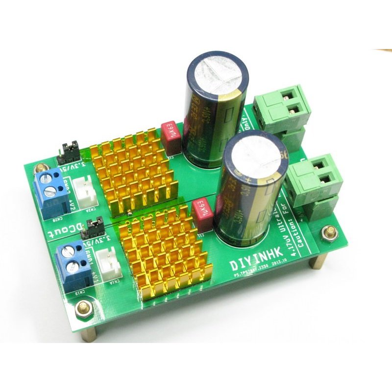
I removed the audio board and placed the Diyinhk power supplies I have inside the chassis. Fits perfectly with small 5v transformer. I bypassed clocks Vcc and Gnd with small value film caps. I am not going to try and fit an SMD to the 20mhz clock resistor pad. That is way beyond my abilities... The wiring is not very good. I used mildly twisted cotton/copper wire because it was the smallest and most flexible gauge I had. The thinnest coaxial I have is still too stiff to fit under the heatsink and definitely too thick for the tiny 20mhz resistor pad.
TPS7A4700 4.17uV Power supply:
But what about 27Mhz for music?
? I talked about the music in the previous post...
For music, I am using Fox Xpresso for 27mhz clock. And it sounds terrific! Sound quality is almost liquid, 'musical', almost too much so. Very interesting. Reminds me of TDA NOS DACs. So I wonder if changing the clock has allowed my soekris to reveal its true qualities? In any case, I absolutely think the clock upgrade is mandatory for the coaxial output to DAC.
I see more 'noise' or grain in Blu-ray and the streaming Netflix I see what appears to be more noticeable compression. On the good side, there is greater resolution and color fidelity is richer with more depth. My guess is the new clock makes the Oppo *very* revealing image quality. So much so, that I realized that HDMI 1 image looks very different from HDMI 2. So I searched google and found out that output 1 uses the Marvell processor, but output 2 is 'pure' or 'direct' image! I now prefer output 2 as it seems more accurate. HDMI 1 is perhaps *too* revealing.
Everything you say here is exactly my experience after getting the power supply and clock upgrades.
What i found out is; the Marvell on HDMI 1 is a 'post' processor. Once you get a clean power supply that improves overall image quality, HDMI 2 actually looks better because its the direct output with minimal video processing. Less processing = more natural image.
- Home
- Source & Line
- Digital Source
- Oppo's BDP105 - discussions, upgrading, mods...