Therefore I advise the use of a fan inside the enclosure (as described previously in this thread). Such fan it make the air inside to circulate, providing a better temperature exchange, for all the dissipating components inside, including the LPM (which however it spread an amount of its heat inside too).
I have a fan that should work. Would drilling holes in the chassis/cover also help. If so, where would you recommend?
The body of the component itself it can come up to 70deg.C, on a max load of 5A. This is a very max load, which is a little bit higher than an Oppo device it use (up to 4 A with two USB ports loaded with hard disks). Else on a average load inside the player (105) it can come up to 55 deg.C. Inside a 105D model, as the power demand is a little bit lower, because the latest processor version, the LPM`s load is even lower.
On a normal use of the player (+ one USB port), the temperature of the LT1083 (body) is approx 50 deg. C. The center of the LPM heatsink it still around 45deg.C. These may be the normal thermal parameters... There are actually the USB ports which it can load quite much the 5v rail of this LPM, especially when a spinning hard disc is connected to the player. Therefore I will suggest to not keep connected a such consumer on USB ports, if it may not be in use.
Okay thanks. The tested the LPM briefly and used spdif/network music playbak and temperature was around 45-50C.
Okay thanks. The tested the LPM briefly and used spdif/network music playbak and temperature was around 45-50C.
Perfect! As it should, also... If you will add a spinning hard disk to a USB, then the temperature it may rise with around 5 deg. more.
Honestly, I think you should not work so hard to make holes in the upper cover... It may not be necessary. I suppose you will find a picture here in the thread, with the fan placed over the main processor heatsink (103 model), and blowing over it (I could also add the complete fan kit to your LPM, but I did not known about your intentions).
The air flow created so (low fan speed), it will help first the processor to keep a lower working temperature, and it will move the air around inside the enclosure, making a better contact with the whole its surface, and finally a better heat transfer to outside world (you may contribute so to the global clime change/warming...
 ).
). The LPM it still have the main heat transmission through the side of the chassis where is placed.
I will suggest you try using your player in such approach, before eventually decide to go to the next step: holes into the cover. Yo may also do some tests, if you may have a temperature probe placed somewhere into the enclosure.
If you will decide to make some perforations into the cover, then the Oppo approach used for 105 models, it will apply quite well in your case too. Two perforations areas on the left/right sides of the cover. With the fan placed over the processor, taking fresh air from outside (right side), it will then blow it out the hot one through the perforations area in the left side, cooling more the LPM too...
Last edited:
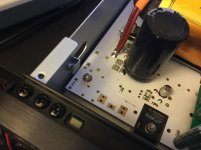
Coris does this screw need to be plastic? It grounds the lpm to the chassis and it seemed like you dont want that but it was not clear from your instructions.
Also I definitely needed to use 2 3mm thermal pads between the heat sink and the chassis.
Also I definitely needed to use 2 3mm thermal pads between the heat sink and the chassis.
Attachments
Last edited:
Coris does this screw need to be plastic? It grounds the lpm to the chassis and it seemed like you dont want that but it was not clear from your instructions.
Also I definitely needed to use 2 3mm thermal pads between the heat sink and the chassis.
No, it should not be a plastic screw. There is a pad under that screw, which is indeed meant to ground the LPM ground to the chassis. This connection is optional, and for cases which it may be needed so (if the LPM it may be used in other, différent devices. That pad is to be connected to the main ground through a trace gap on PCB. This connection is not made in your case.
Your LPM, and its heatsink are correctly grounded (if the heatsink does not touch the chassis). Else, the thermal pad it isolate it very well.
About the fan, well, I do not want to give you up, but I do not like that approach. There is a little bit unfortunate, that I was not knowing about your fan intentions. I will send you the right things...
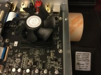
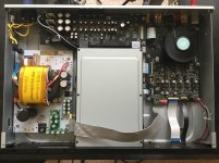
As I can see in your last picture, you keep connected the flat cable to the audio board, while that is not powered. This is not right. You should disconnect that flat cable from main board to the audio one. Else you will experience some issues on HDMI outputs. The audio board is powered on 3,3v rail from main board, and it "report" errors, because it have no main power... No flat cable, no errors...
Last edited:
No, it should not be a plastic screw. There is a pad under that screw, which is indeed meant to ground the LPM ground to the chassis. This connection is optional, and for cases which it may be needed so (if the LPM it may be used in other, différent devices. That pad is to be connected to the main ground through a trace gap on PCB. This connection is not made in your case.
Your LPM, and its heatsink are correctly grounded (if the heatsink does not touch the chassis). Else, the thermal pad it isolate it very well.
About the fan, well, I do not want to give you up, but I do not like that approach. There is a little bit unfortunate, that I was not knowing about your fan intentions. I will send you the right things...
As I can see in your last picture, you keep connected the flat cable to the audio board, while that is not powered. This is not right. You should disconnect that flat cable from main board to the audio one. Else you will experience some issues on HDMI outputs. The audio board is powered on 3,3v rail from main board, and it "report" errors, because it have no main power... No flat cable, no errors...
The flat cable is not connected to the audio board. I think its the angle of the photo makes it look connected...
Whats wrong with the fan?
OK, about the cable...
Well, about your fan, I think it is not just the right mounting approach... That tape it will miss its glue properties in time, in a part because that heatsink it get warm however... The fan it also vibrate, and in time it can be disclosed from its place and land on the board, while spinning... That mounting it works for a while, but it looks more like an improvisation. The contact surface for the adhesive tape it may not be enough for a stable construction, because the heatsink configuration...
Here is my proposal (picture).
Else, how do you solve the fan start up and functioning only when the player is on?
I may suggest to power it from a USB port, because the power it fit quite well
Attachments
Last edited:
OK, about the cable...
Well, about your fan, I think it is not just the right mounting approach... That tape it will miss its glue properties in time, in a part because that heatsink it get warm however... The fan it also vibrate, and in time it can be disclosed from its place and land on the board, while spinning... That mounting it works for a while, but it looks more like an improvisation. The contact surface for the adhesive tape it may not be enough for a stable construction, because the heatsink configuration...
Here is my proposal (picture).
Else, how do you solve the fan start up and functioning only when the player is on?
I may suggest to power it from a USB port, because the power it fit quite well
Ok. Good points. I agree it is not a good long term solution...
Does using the fan also improve other areas besised video? I think the spdif playback sounds better after adding the fan...
As I could observe (experienced) myself, a good ventilation (low working temperature for the main processor) it have an positive impact, mainly over the image/video stage of the player.
For the sound quality improvements (in a simple way), the most important is the system power quality, and the replacement you already did is just the right way to do it.
In general, and in my opinion, a lower working temperature for a processing unit/device it lead to an increasing quality for the overall final result of that processing. How and why in details, it still to be clarified, discussed, explained, etc. At least the explanations in this respect, it may be less important. The most important is the result in fact...
Well, my point of view in this field...
My impressions so far of the LPM is that it has a big impact on image quality and hdmi audio. Stock 103 PS the hdmi audio was somewhat muffled. I blamed the small speakers (Mark Audio full range) at first and their poor placement. After installing the LPM the sound quality improved dramatically. I can hear minute and tiny details and the voice quality is superb. Unfortunately my main 2-channel setup does not use hdmi so I can't compare it in a better setup. Image quality has deeper blacks and more film-like texture with improved contrast. Almost like mild Darbee effect.
With my 2-channel setup (MTMs designed by Jeff Bagby + subs), using ethernet streaming via Oppo coaxial to Soekris dac, the improvement vs. stock is not quite as dramatic but audible nonetheless - cleaner treble and low noise floor. I have made changes with my 2 channel setup while configuring the Oppo and LPM over the past weeks so it's a little harder for me to make a firm comparison.
All in all, definitely worth the upgrade. I love movies so to have such great image and audio playback quality I consider a huge plus. I'd like to get the clock upgrade eventually.
Thanks Coris!
Last edited:
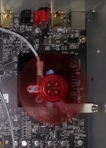
The approach of one master clock for 105D player is now tested and it works excellent. I already made the modifications on my divider board for a new version of it.
The frequency of one master oscillator of 216Mhz (SAW), is divided by two parallel Ghz rated devices. One divider it provide the clock signal for DAC (108Mhz), while the second divider it provide clocks for main processor, Darbee, and HDMI chip (27Mhz/54Mhz). All powered by battery (as usual...).
While working on this 105D device, I found out (with enough insatisfaction) that for this model does not work anymore the USB isolated approach. The communication between USB board and main processor is now bidirectional, and therefore the digital isolation is no longer possible. Else, the USB board it still be improvable, both for its power system, as for the oscillators on board. Instead of being powered from main board, it have now in my approach. its own dedicated linear PSU.
Hi All
Oppo 105D audio power supply question if anyone knows the answer.
What transistors ics are U33,U35 U31,U23 and Q6 on the stereo audio board?
Ps the U 33 and U 35 seem to run very hot
Many thanks
John
ps removing my switched attenuator and going straight to the power amp was an immediate improvement.
Hi All
Oppo 105D audio power supply question if anyone knows the answer.
What transistors ics are U33,U35 U31,U23 and Q6 on the stereo audio board?
Ps the U 33 and U 35 seem to run very hot
Many thanks
John
ps removing my switched attenuator and going straight to the power amp was an immediate improvement.
U33,U35 U31,U32 are regulators for +/-15v, +/-12v... LM2941/90, LM317/337, Q6 is the power transistor for AVCC regulator...
U33,U35 U31,U32 are regulators for +/-15v, +/-12v... LM2941/90, LM317/337, Q6 is the power transistor for AVCC regulator...
Many thanks Coris.Much appreciated.
- Home
- Source & Line
- Digital Source
- Oppo's BDP105 - discussions, upgrading, mods...