.
PART TWO
CIRCUIT DESCRIPTION:
OTA: Operational Transconductance Amplifier
The SOIC device contains within its package one transconductance amplifier and a unity gain buffer. A "transconductance" amplifier is an amplifier that takes an input voltage and outputs the signal in form of a current. It is in fact a current-source. The output signal can then be 'dumped' into a fixed value resistance, across which a voltage signal develops, which is then buffered for the final output.
The OTA has a very large bandwidth, very high linearity and can be used without feedback.
The OTA also has another simplifying feature: If we were to use the same opamp solution as before, then for two channels, three SOIC opamps would be needed, but since our OTA does the summing already, a final summing stage is no longer required.
So unbalanced, only two SOIC devices to cover L & R, not three.
For balanced, four SOIC devices in total is required.
Circuit operation, where do we start?
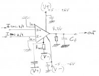
The Input from the DAC: The internal Z of the DAC is 781R per phase. The OTA has two inputs '+" and "-" and these are asymmetrical. The "+" is very high input Z and "-" is very low Z.
If we keep R1 and R2 very low, say 10R or lower, then considering the DAC's relatively high Z output at 781R, we will definitely be operating in "current" mode.
But note that the DC offset on both of the DAC's phases are +1.65V, so the small value of R1 and R2 basically means we are grounding the DAC's outputs. This means that we will trade the +1.65V offset voltage for 2.1mA offset current.
IF A DAC HAS AN OFFSET VOLTAGE - NEVER GROUND IT LIKE THIS - ONLY THE SABRE DAC !!!
If we could get R1 and R2 symmetrical (this requires work to sort out), then in theory the DC on the final output would be zero Volt. But the Elna Silmic coupling capacitor will need to be retained for simplified manufacturing purposes and for the safety issues that made Oppo use them in the 105.
But for us: We can eliminate the C4 Silmic cap manually later. The good news is that the DC will be able to be nulled by us DIY guys and those who work on other people's players. The solution should prove the simple addition of a trimpot. But such a solution is simply not practical with the stock player. We can make ours completely DC coupled throughout!
Now please note R3 - this is where the OTA's current is dumped, so the gain is set by this value. The signal that appears across R3 is now buffered to the main outputs.
It is clear that the balance of R1, R2 and R3 is what will set the output level to 2.2V approx. It is expected that R3 will be in the range of 22K.
The output of the buffer stage is current limited by R4, a suitable value should be 220R. The buffer can swing 8V p/p into 220R safely. Please note that the Mute shortens the output, but of course the DAC also goes into Mute, so this is a double-safe device.
The final R5 is just a grounding resistor, value not critical and 47K seems to be commonly used here.
Now for C1, C2 and C3. These are of course used for passive filtering. The C1 should be the dominant pole. That means it is the lowest frequency. This C1 does indeed affect the sound and its value should be chosen after careful listening. Something like 0.33uF is in the ball-park.
The next C2 is a pole that is somewhat higher, but likely value is 33pF or 47pF.
The final C3 may well be optional. Together with R4 (220R) this forms what I call a "Ben Duncan" filter, since he was the first one that I saw use it. Typical value may be 470pF.
The only value not discussed is R(i) which sets the current in the OTA, the likely value is 180K-270K range.
So there you are.
In PART THREE: Will discuss two other areas that Oppo could make a significant improvement and should be able to do this as no added cost. They are remarkably simple and highly effective.
Cheers, Joe
.
PART TWO
CIRCUIT DESCRIPTION:
OTA: Operational Transconductance Amplifier
The SOIC device contains within its package one transconductance amplifier and a unity gain buffer. A "transconductance" amplifier is an amplifier that takes an input voltage and outputs the signal in form of a current. It is in fact a current-source. The output signal can then be 'dumped' into a fixed value resistance, across which a voltage signal develops, which is then buffered for the final output.
The OTA has a very large bandwidth, very high linearity and can be used without feedback.
The OTA also has another simplifying feature: If we were to use the same opamp solution as before, then for two channels, three SOIC opamps would be needed, but since our OTA does the summing already, a final summing stage is no longer required.
So unbalanced, only two SOIC devices to cover L & R, not three.
For balanced, four SOIC devices in total is required.
Circuit operation, where do we start?
The Input from the DAC: The internal Z of the DAC is 781R per phase. The OTA has two inputs '+" and "-" and these are asymmetrical. The "+" is very high input Z and "-" is very low Z.
If we keep R1 and R2 very low, say 10R or lower, then considering the DAC's relatively high Z output at 781R, we will definitely be operating in "current" mode.
But note that the DC offset on both of the DAC's phases are +1.65V, so the small value of R1 and R2 basically means we are grounding the DAC's outputs. This means that we will trade the +1.65V offset voltage for 2.1mA offset current.
IF A DAC HAS AN OFFSET VOLTAGE - NEVER GROUND IT LIKE THIS - ONLY THE SABRE DAC !!!
If we could get R1 and R2 symmetrical (this requires work to sort out), then in theory the DC on the final output would be zero Volt. But the Elna Silmic coupling capacitor will need to be retained for simplified manufacturing purposes and for the safety issues that made Oppo use them in the 105.
But for us: We can eliminate the C4 Silmic cap manually later. The good news is that the DC will be able to be nulled by us DIY guys and those who work on other people's players. The solution should prove the simple addition of a trimpot. But such a solution is simply not practical with the stock player. We can make ours completely DC coupled throughout!
Now please note R3 - this is where the OTA's current is dumped, so the gain is set by this value. The signal that appears across R3 is now buffered to the main outputs.
It is clear that the balance of R1, R2 and R3 is what will set the output level to 2.2V approx. It is expected that R3 will be in the range of 22K.
The output of the buffer stage is current limited by R4, a suitable value should be 220R. The buffer can swing 8V p/p into 220R safely. Please note that the Mute shortens the output, but of course the DAC also goes into Mute, so this is a double-safe device.
The final R5 is just a grounding resistor, value not critical and 47K seems to be commonly used here.
Now for C1, C2 and C3. These are of course used for passive filtering. The C1 should be the dominant pole. That means it is the lowest frequency. This C1 does indeed affect the sound and its value should be chosen after careful listening. Something like 0.33uF is in the ball-park.
The next C2 is a pole that is somewhat higher, but likely value is 33pF or 47pF.
The final C3 may well be optional. Together with R4 (220R) this forms what I call a "Ben Duncan" filter, since he was the first one that I saw use it. Typical value may be 470pF.
The only value not discussed is R(i) which sets the current in the OTA, the likely value is 180K-270K range.
So there you are.
In PART THREE: Will discuss two other areas that Oppo could make a significant improvement and should be able to do this as no added cost. They are remarkably simple and highly effective.
Cheers, Joe
.
Last edited:
My suggestion is to use transformers with SABRE and be done with it. It sounds amazing - the best by far.
Transconductance solution sounds inferior. But, for those who are still tempted to waste their time - I included the circuit that will give very good results, but not as good as transformer solution. By the way, the rest of information can be found on MAXIM web site. I played with this circuit approximately 10 years ago...
I must add that my preferred I/V stage is still OP based, with fair amount of feedback. However, this I/V solution works well only with the 1704's that have minuscule current-out capabilities and simply has to be used with decent amount of gain that follows. I've learned to appreciate AD811's, properly implemented. In the case of 1704, everything else I tried (passive, transformers, valves(ouch..)) was inferior. AD811’s have allowed 1704’s to shine and impress.
SABRE DAC's? Yeah, they sound good and due to their high Vout (Iout) capabilities, simply beg to be used with simple transformer solution.
Attachments
My suggestion is to use transformers with SABRE and be done with it. It sounds amazing - the best by far.
If you have looked elsewhere on diyaudio.com, you will have found my contributions on transformers and Sabre DACs.
BUT... I think you are missing the point... what this exercise is all about:
Oppo is not going to use transformers.
Also, have you used the exact example I have shown, whereby the DAC's output is pulled directly to ground? If not, then you have not heard what the Sabre DAC sounds like when it operating in that mode.
I have heard both.
Whichever, we could go on discussing this, but the aim of the exercise is to show HOW a new stock player can be improved, not by DIY means and getting the best out of it (we will STILL be doing that), but by way of simply changing some things for the better and make a better product at that price point.
BTW, not thinking of a MAXIM device. Availability is an issue as well (wafers n/a), and you will note I discussed that issue as well, and that it must be SOIC 8 Pin.
Cheers, Joe
.
Last edited:
Played with OPA860 as well during my 1541 days... anyway, why are you discussing a mass-produced stock-player improvement solution on DIY forum? Don't you think that such solution, if implemented by OPPO, would leave DIY-ers with nothing to do? And why the need for 2 weeks advanced notice on your (non)revolutionary solution, and 3-tome long (non)educational posts?
By the way, OPPO-branded output transformers could be just what OPPO needs to propel their products to a High End audio nirvana, firmly establishing their name as serious High End Hi Fi brand - especially if they used a silver wire windings. This would easily qualify as the ultimate SABRE implementation on the market.
By the way, OPPO-branded output transformers could be just what OPPO needs to propel their products to a High End audio nirvana, firmly establishing their name as serious High End Hi Fi brand - especially if they used a silver wire windings. This would easily qualify as the ultimate SABRE implementation on the market.
By the way, OPPO-branded output transformers could be just what OPPO needs to propel their products to a High End audio nirvana...
Trust me, Oppo is not going to entertain that idea.
Please don't be a troll, OK?
Have you got manufacturing experience?
Have you owned an Oppo 95 or 105?
Again, please, I don't want to have anything to do with a troll.
As you are in Sydney, call me on 0412-203382 - maybe there is a context here that you are missing out and I would like to discuss it in a non-confrontational manner. I don't really like this sort of aggro stuff.
Also, there is a trick that you can try with that Lundahl transformer and I would be happy to tell you about it.
Last edited:
Troll? No one’s called me a troll before. You are the first, so you've just gained my devoted attention.
The suspense build up towards your “revolutionary” analog-out solution is nothing but attempt to continuously promote your business and services you do for the money and your personal benefit. There is a place for such activities on DIY Audio forums – it is called vendor forum.
If you have something to share with DIY-ers on this particular thread – do it in a single post, show the diagram with all the part numbers. The colourful, bold signature links promoting your business are insulting, especially when mixed with your attempt to educate.
Keep the tricks for yourself. I'd gladly accept the offer from a DIY-er, though.
I think the idea Joe shows here is interesting, and it deserve a closer look. Why not try it?
LM13700 is a chip which it may do this job... I chosen it only as example of such circuit types. I do not mean that one may use exactly this one...
I personally can not find something wrong with Joe`s didactic way to explain the concept. But I could notice the suspense aspect of the coming "news"...")
P.S. If Joe will agree to remove his "multicolours" signature from his posts, then the commercial/advertising nuances of his interventions will may disappear too....
LM13700 is a chip which it may do this job... I chosen it only as example of such circuit types. I do not mean that one may use exactly this one...
I personally can not find something wrong with Joe`s didactic way to explain the concept. But I could notice the suspense aspect of the coming "news"...
P.S. If Joe will agree to remove his "multicolours" signature from his posts, then the commercial/advertising nuances of his interventions will may disappear too....
Last edited:
If you have something to share with DIY-ers on this particular thread – do it in a single post, show the diagram with all the part numbers.
I am not going to react negatively as you have done.
In over thirty years I have been a great supporter of the DIY cause and have hundreds of witnesses (and lots of friends) to prove it - like several thousand hours developing the Elsinore Loudspeaker Project and in no way did it for the money, because there was no money in it.
To prove you totally wrong, the day before I also posted this: 40W Transconductance Amplifier
This "Current Amplifier" using an inexpensive Power Chip means more can apply current drive a la Esa Meriläinen -especially fullrange loudspeakers and was supported via private emails with Dave Planet10 moderator leading up to posting the FULL DESIGN. Having built many chip amps (and published the designs), this sounds like no other Power Chipamp, because it outputs current. It even measures differently. I will get a big buzz if many build it and don't expect to make a cent, life is so much more than about accumulating money.
So my record, just from a few examples here (and there are more) has been pretty good, and enjoyable, and a challenge, and a buzz.
Using transformers, see Buffalo II & Transformers - I have no financial gain to make for contributing on a forum that promotes Russell White's Twisted Pear Buffalo DACs, zero gain.
If you are using the ES9018, then try this and this the result one user had.
But have you had any experience with Sabre DACs at all?
If you do, note that it's high output Z makes it less than ideal with transformers, and paralleling up all four phases is a must and when dual-mono Sabre DACs are used, then at least (with 8 phases) you can get the source Z into the Primary below 100 Ohm. Indeed, a number of people I know don't like the Sabre DAC they heard, and when we investigated it, they had voltage mode in common. The comments were "glary" and "tonally light and bright" - and my suggestion of pulling the DAC to ground can only be done with the Sabre DAC, and then it sounds rather differently. Among other things, the BASS now appears in balance. Body and fullness that was missing in voltage mode.
BTW, in the Oppo 105 and like future designs, we have only a single phase - 781 Ohm. That is per phase and totals 1562 Ohm into the Primary of a transformer. Now, you can see WHY Oppo will never opt for transformers.
You seem to think that I am against transformers, but that is not the case. I have used post-DAC transformers for 15 years, I have even had some custom made. Like you I have also used AD811 as I/V Converter, and that was TWENTY years ago with Philips 1543A DACs... yes, I have been around for a while... maybe too long...
If you have not had any experience with the Sabre DAC, have you not been just a bit too quick? Just asking.
Hmmm, our Sydney is raining today - but let it not rain in our hearts.
Cheers, Joe
.
Last edited:
The main advantage of an OTA is it's programmable transconductance, and that's about it. An OTA is basically less accurate, less linear and also exposing a temperature drift that can not be compensated for. The circuit will sound inferior to simple, natural presentation obtained from either the transformer based stage (with SABRE), or with AD811 (with 1704's). The most annoying problem was the change in sound character as the DAC enclosure warmed up. The change is subtle, but it is detectable.
The transformer solution you are suggesting does not take in to account the reflected impedance of the interconnects / pre amp on to the primary impedance “connected” in parallel with 2 X 330 ohms resistors.
The fact you have free advertising with every single “revolutionary” post you do on DIY forum is insulting to others who don’t do the same thing, and post their commercial solutions on the dedicated forums created specifically for that purpose.
Either show your solution you've been bragging about- but showed nothing in fact so far, or remove the advertising material. I come here to see what DIY-ers do to improve the sound. Few members may think it is okay to have free advertising, but I do not and I find it offending.
Joe,
I suspect that this guy is either a participant in, or a follower of, a particular semi-DIY ESS9018 DAC project which is active on this forum, just like I myself am. I have not yet tried this voltage-mode transformer-ouptut configuration on my unit, but I most definitely to plan to do so (as one of several topologies which I plan to experiment with, including yours). But the response (in another thread) to the topology which he referenced here has been tremendous so far.
FWIW: I also have serious reservations about driving a transformer from such a high impedance output. Although in the case of this other DAC, the outputs have all been paralleled to achieve a net Push-pull output impedance of 390R, which is much higher than seems wise to me as well. But if I understand the topology of the 105, it does not have all of 4 parralled outputs the way that the 95 did, does it? If this is correct, then that would mean that the net output impedance on a 105 might be double that (or even more than double) of the 95, or of this the other. Again, if true (please forgive me if I happen to have my facts wrong on this), then such a raw transformer output would be far less suitable for a 105, than it would be for a 95, or the DIY DAC project of which I am referring to.
I know that you don't know me by my alias on this forum (but you actually do know-of me, I'll introduce myself in a PM to you). And I sincerely hope that you do not take my post as trolling; it is most definitely NOT intended as such. I am merely attempting to provide a little insight for you regarding a rather hot, and semi-releated, thread on this forum which is likely to inevitably bleed-over into this thread to some degree due to the use of the same ESS 9018 DAC chip inside of each of these units.
Thank-you very much for all of your contributions on this subject. I can't wait to try my DAC in some variation of the super-current mode which you describe. I have gleaned many insights from (silently) following your work over the years.
Right you are about transformer drive, Joe. Many people here have never noted what happens when you drive a transformer with a relatively high impedance.
Thank you for backing me up.
Joe,
I suspect that this guy is either a participant in, or a follower of, a particular semi-DIY ESS9018 DAC project which is active on this forum, just like I myself am. I have not yet tried this voltage-mode transformer-output configuration on my unit, but I most definitely to plan to do so...
What a difference in tone to that other guy, thank you. It makes all the difference.
I have nothing against Boky and I have not made a single criticism of him that I know of. His past contributions have been OK with me and we do have more things in common than maybe he realises. I just don't understand the sudden change in tone? He seems to be offended (actual word he used) by the link below to Custom Analogue Audio, but he overlooks that it also has a large DIY component and in fact, it is unusual for a website to straddle across the line - so it does not fit a pure commercial website definition in the classic sense as that would not contain totally non-profit DIY.
Other moderators here on diyaudio.com seems to understand that. Only Boky has so far made an issue of it. There is a vendor's forum, but by definition I am both a vendor and been a genuine DIY'er from the cradle (thanks to my Dad).
Boky is here in Sydney, Australia. We have our own stereonet.com.au forums. A couple of times my name was made mentioned off, and somebody contacted me and suggested I should chime in. It must be an Australian thing, but right away the accusations started, how dare I, a 'commercial' entity appear on THEIR forum. But I had been invited to make a comment. Look at the records, I cannot be accused of using Stereonet to promote myself and my own products, when in fact I don't have a lot of posted messages there, it is not a DIY forum. But this has happened a couple of times in Australia, it seems an Australian thing, sadly. But diyaudio.com has not been a bit more flexible and I think there are people on it that otherwise would not, and that would have been sad or we would all be worse off.
Re Txs: I like transformers, as Boky does. I like the AD811, his fave rave, I do too.
There is that Buffalo thread on transformers, where I believe I have made some decent contributions. One of the guys in Malaysia uses a custom made (here in Sydney) transformer that was made according to my design - a quad-filar wound 1:1 transformer, somewhat expensive. I am not against using transformers at all. I STILL use it with other DACs too. It they work, I will use them, no fear.
One day I would like to meet Boky - being in Sydney, he is my nearest neighbour so-to-speak.
I would love to play my "Trans-Amp" for him - pure DIY as there will ever be. I am no going to make them. Not everything in life is measured in dollars, God gives us sunshine and doesn't charge a cent.
Cheers, Joe
PS: I have changed my signature on the bottom, I hope it suffices.
By the way, OPPO-branded output transformers could be just what OPPO needs to propel their products to a High End audio nirvana, firmly establishing their name as serious High End Hi Fi brand...
That proves, we in fact are aiming at the very same thing - it just comes down to what will be acceptable to Oppo.
But from my view, the exercise is to look at the Oppo '105 and see what way they may feel comfortable to improve it.
BTW, I don't want to pick a fight with you, but you have said elsewhere that OTA produces 1% distortion, specifically the AD844.
I can happily verify that it does not - with an actual measurement, see attachment.
THD 0.08% and THD+N 0.028% - this is from a test disk -20dBFS.
No feedback at all.
Please also look closely at the proposed schematic and the accompanying text where proposed values were shown (which I suspect are going to be very close in the real-world). So really did lay it ALL on the line.
I was surprised nobody has guessed the active device, OPA860 (alas the 660 would have been preferred), as there were a number of clues. By the next post, ALL that I know has been revealed.
I hope Coris will also build this - so EVERYTHING will be on the table. It may never even get into an Oppo player (other than mine here), but so be it.
Cheers, Joe
PS: Note the change in my Signature below, never desired to offend anybody.
PPS: Please note, this may all turn out to be a monumental failure and not work out at all, and what has been posted is there to stay - so I will have to wear it. But sometimes you have to be brave.
.
Attachments
Last edited:
I also was a little surprised that no-one guessed what the active device was, as there were quite a few hints, that I was referring to an 8 pin SOIC, readily available (I just bought 10 from our old friends in Chester Hill) and nexpensive, that it was a major American chip manufacturer, in fact Texas Instruments.
I thought it would have been guessed by now.
It can swing 8V p/p from 5V rails and hence can supply the same output as the ES-9018 with some additional headroom. Need to aim for 2.2V RMS.
The device is indeed OPA860 - descendant of OPA660 - and yes, it is not as good on paper, as Charlie Hansen has pointed out re the Buffer section. But the OTA I understand is fine. The Buffer is the question mark? It is closed-loop where the 660 was not. But limiting the bandwidth on its input will help - so it is a compromise, but I think it should be tried. The wide bandwidth of the Buffer (4000V/us) indicates current feedback - a la AD811 - and then maybe not bad at all. But it is what we have got and the OTA will still be zero feedback.
(Note 220R limiter on the output as discussed earlier, so swing up -1V of the rails is a given.)
Since we know that the ES9018 operates of 5V (in two phases) to give about 6.3V output, we can match that and with some headroom with 5V rails used in the OPA860 (just wish we could have 660 in SOIC).
AD844 is not an option, not SOIC.
I hope some time next week to get a working example going and ALL will be revealed. I hope that Coris will also build it and report back.
If this is to work (and I am not saying there are no other approaches), then it needs to be a low distortion solution that we can compare with the OTA distortion measurement made in #616, where the OTA is running 10.7V rails.
Whatever the result, we shall find out.
Please note, if this does not work, I am at least the one brave enough to risk falling on my face, if this turns out to be a colossal failure.
Hopefully not. If it works, this is going to be the most cost effective way to do it - at lest the way I look at it.
Around mid next week I intend to get busy on this - and worts and all will be reported here.
I have questions in my own mind that I want to ask here, re the Silmic output cap, If a stable small amount of DC bias for the cap, maybe that would be a good idea? I measured no DC other than small mV, so Oppo is not biasing the Silmic. Others may have more experience with using this cap. I favour at least some DC. (Yet for us, find a way to null it out.)
Cheers, Joe
Last edited:
Thanks for the input, Joe. I tend to agree with you, BUT I personally don't know of any chip that will make it happen. Perhaps an IN-AMP might be the closest solution.
Instrumentation opamps are available in a single package. Yes, it could be done that way. And you can bring that +1.65V offset to ground via two 3R3 (which is a value I have used) no problem and the input would be symmetrical, unlike OTA. Yes, it would work, but my heart is set on an OTA solution because I like what it has done (and so have others who have heard it) and the OPA860 is the closest to the ideal I can see.
Next week... I will get going on this.
Cheers, Joe
- Home
- Source & Line
- Digital Source
- Oppo's BDP105 - discussions, upgrading, mods...