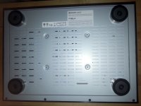
Have you ever wondered how it looks the bottom of the 205 player?
Remembering the expanded 3D picture of the device published by Oppo, I thought that this model it will have indeed a very good passive ventilation, with the whole cover perforated, and the chassis too (as shown in the 3D simulation).
Well, all this is not true at all. Look hereby how few perforations the whole perforated bottom of this model it have, where the air it can in fact get into the enclosure...
Else, the boards inside are perforated a lot, as the cover too. But how the air it can circulate inside and take the heat outside the enclosure, if so little fresh air it can get in? I really can not get it why the designers have perforated a lot one layer of the enclosure`s bottom, if the second layer it not fit
accordingly for the same ventilation holes...
Attachments
Last edited:
Have had my 205 for a week. Can confirm balanced out is harsh, compared to my TwistedPear BuffaloII Dac, on which I use balanced & unbalanced simultaneously to bi-amped speakers, balanced to mids/trebles, unbalanced to bass. TP B-II is same family DAC chip as in Oppo, & sounds much better, IMO. But I need Oppo for other features, so have to either change to unbalanced-only out, or fix the balanced outs. Is the Wima replacement mod simple, do they just replace Electrolytics with same value Wima MKP? And Coris, please PM me re: pwr supply.
Thanks to all for great discussion.
Thanks to all for great discussion.
Last edited:
HP out no good for me: it disables other outputs, so bi-amping won't work.
Currently using HQ DAC unbalanced for mid/treble, processed DAC FL/FR unbalanced for bass.
Sounds better than balanced output, but still not as good as TwistedPear B-II!
Need to install Wima bypass caps to fix balanced output!
Time to plan......
Currently using HQ DAC unbalanced for mid/treble, processed DAC FL/FR unbalanced for bass.
Sounds better than balanced output, but still not as good as TwistedPear B-II!
Need to install Wima bypass caps to fix balanced output!
Time to plan......
Burn-in my 205 for one week now, the sound of the 205 has been stabilized... The sound from the XLR stereo outputs lacks the depth of the sound stage... So, I am gonna sell my 205, and stick with my original DAC by LKS Audio (dual 9038Pro running in mono-mono):
https://www.shenzhenaudio.com/l-k-s...bu-for-dop-usb-i2s-optical-audio-decoder.html
https://www.shenzhenaudio.com/l-k-s...bu-for-dop-usb-i2s-optical-audio-decoder.html
The 205, as the all other Oppo models (now in a kind of tradition), it need improvements to perform as it should and most important, as the hardware of these devices are capable to provide...
As the XLR output of this model is not the best one of the player, it is quite special for a so new, and hardware capable unit. Hopefully this it can be fixed.
As the XLR output of this model is not the best one of the player, it is quite special for a so new, and hardware capable unit. Hopefully this it can be fixed.
The 205, as the all other Oppo models (now in a kind of tradition), it need improvements to perform as it should and most important, as the hardware of these devices are capable to provide...
As the XLR output of this model is not the best one of the player, it is quite special for a so new, and hardware capable unit. Hopefully this it can be fixed.
Hi Coris, I completely agree. However, the design of the I/V, LPF stages need to have a big "surgery" in order to squeeze every drop out of the new ESS chip. Also, the power supply needs to be modified. The Op amp route of the I/V stage needs to be redesigned. LM4562 is is not a good choice for I/V.
By the way, I have the ESS 9038Pro's data sheet, I am thinking how to disclose it, maybe we can exchange info using e-mail: stevesun11001@gmail.com
Last edited:
Well, finally the DAC clock is revealed
I have to say that is very difficult to remove that shield. The dissipation through the ground plane of the board is huge. I use 80w soldering iron, and it was not enough. Finally I have to cut the shield in pieces, and then unsoldering the parts...
This clock is for the multi channel DAC, but I presume the stereo one is the same design.
It was really necessary the shield over that already shielded oscillator? I don`t think so actually, for the quite simple clock circuit... However, the design approach it have a nice and more sophisticated aesthetically look from outside....
Fortunately, there is not necessary to take out the shield, but is is only enough cutting the signal trace, injecting so a new clock signal (and maybe cutting the power for the remaining oscillator...).
Attachments
Last edited:
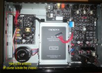
Dismounting a little bit the device, I could observe that there is a gap of 2 mm in between the two bottom layers of the chassis. So there is enough space for the air to circulate and get inside the enclosure, even thought the perforations of these layers does not coincide. Clever!
I have to modify my previous assertion about bad passive ventilation for this model. The inside bottom layer of the chassis it consist of a 1,5mm thickness steel plate. Very solid indeed!
The optical drive is mounted very close to the bottom. So it is much more easy to mount it on elastic suspensions... But the flat cable of the LPM it will have to be routed over the drive...
And some not so happy news (for me): the position of the SMPS board in 205 is designed so that it not fit for my LPM board...
Oppo decided to keep the bolt in the middle of the SMPS board, even it is no any corresponding fixing hole on that board... Just for make me problems...
So, I have to adjust my design and produce another boards fitting for 205 model. Approx two weeks delay for the LPMs for this model (and then the boards it will fit for all the rest, old and new)...
Last edited:
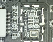
Examining closely the clock design for the DAC chip, we can see an extended filtering approach on the power line of the oscillator. Is seems Oppo was very preoccupied (for this model) by the HF noises impact over the player system and functionality of particular stages. Good!
It intrigue my a little bit the choice of Oppo designers when they placed a RC filter on the oscillator output (R605 and C639). It looks like they wanted to minimise/limit the levels of the harmonics coming out of the oscillator, beside the fundamental frequency. I do not know yet the values of these filter components. Also remain a open question about the type of this oscillator... Maybe someone know/recognise the marking on it... It may be this oscillator a SAW type one?
The preoccupation of Oppo designers to minimise the impact of the HF noises inside the enclosure itself, as the one coming from outside, is noticeable also in the chassis design. The two layers bottom with not matching ventilation holes it is one of the solutions to increase the shielding properties of the chassis bottom, while keeping a good ventilation capability for the enclosure.
I could see also that the SMPS section/board is in this model very well shielded, by a strong and large area covering steel case. If this SMPS board it need to be so well shielded for this model, what about the 203 model, where the same board is let it fully uncover inside the enclosure?
The toroid for DAC/analogue audio stage of the player it is shielded (in a cheaper way also, but good enough).
The optical drive it still have a full plastic body, covered by a metal (steel) sheet on its topp. Placing the drive right near the bottom, it also improve the shielding of this device for its down side too.
It may be this preoccupation of the designers for a good HF protection of the inside components and a improved shielding, due to the use of the WiFi emitter`s antennas on a side of the enclosure? We may not forget that we have here a quite strong UHF emission, very near to the enough sensitive parts. Well, the main frequency of this WiFi section is very high, but harmonics it can go enough low to disturb the sensitive stages. Also interference of these very high frequencies with some other EMI perturbations, it can have impact over the particular stages inside the system. This it can explain also the extra shielding for the 100Mhz clock stages for DACs. This it can explain the special care of the designers to shield very well the SMPS board inside the device.
Even thought the very improved shielding for the 205 model, against inside and outside HF disturbances, we still have a harsh sound on XLR output...
What about to just disconnect the WiFi antennas, and use only the cable network interface?
The wireless is very convenient to use, but a quite strong emitting device right on a side of the player, it may be so safe for the also very high frequencies of the digital signals, clocks frequencies, and so on, inside an enough complex digital/analogue system?
I think I will get rid of this WiFi stage (antennas)...
Last edited:
OK so we see a 100 MHz clock, And it is certainly nice to have the clock circuit in a shielded box .
Are the Wi-Fi antennas not outside the chassis?
For the harshness, I would suggest first replacing the decoupling capacitors and bypassing the electrolytic output coupling capacitors With a wire.
As far as installing your LPM, please show us a detailed installation diagram, will we need to disassemble anything other than the SMPS?
The analog side of this unit is already quite warm. How much more heat is generated by the new power supply, and therefore is the fan now more necessary?
E
Last edited:
Burn-in my 205 for one week now, the sound of the 205 has been stabilized... The sound from the XLR stereo outputs lacks the depth of the sound stage... So, I am gonna sell my 205, and stick with my original DAC by LKS Audio (dual 9038Pro running in mono-mono):
https://www.shenzhenaudio.com/l-k-s...bu-for-dop-usb-i2s-optical-audio-decoder.html
My experience with the modified 105 was that you can only get so far with this in 2 channel.
After I replaced it with a Vega DAC,there was a huge improvement. I also replaced the 105 streamer with a dedicated Aurender streamer. If you're only using two channel, you will do much better with dedicated separate audiophile components.
I am primarily using the 205 as a 4K UHD Blu-ray player, and it is fantastic at this. As a side benefit, it is also my last remaining SACD player, and so I want to optimize the analog outputs. I am not using the seven channel analog outputs anymore as I am using an anthem preamp.
E
OK so we see a 100 MHz clock, And it is certainly nice to have the clock circuit in a shielded box .
Are the Wi-Fi antennas not outside the chassis?
For the harshness, I would suggest first replacing the decoupling capacitors and bypassing the electrolytic output coupling capacitors With a wire.
As far as installing your LPM, please show us a detailed installation diagram, will we need to disassemble anything other than the SMPS?
The analog side of this unit is already quite warm. How much more heat is generated by the new power supply, and therefore is the fan now more necessary?
E
Yes, the WiFi antenna is outside the chassis, but included into the chassis dimensions. In my opinion, after a first examination of the device, there was taken some extended precaution or measures for minimising the HF/EMI interferences into the player system. These measures are not taken just by chance, but based on some analyses. We do not know the details of what they found out, but I think the existence of a enough strong emitting device included into this system, it may have some important impact or influences.
The shielding box of the WiFi antenna is very carefully sealed inside with some conductive material. The shielding cover for antenna in 205 model is made of a thicker steel than the one in 203 model. There are some aspects here, I think...
Off course the harshness it can be fixed, but my point is that this exist in a finished product, so as it is. The XLR which it should, by definition be the best output, and it was for previous models, it is not in this device.
The installation of the LPM it should be just plug and play. Therefore I adjust right now the design of the board, and I will produce another batch for a perfect fit.
Well, for installation one should reach the power connector to the main board to remove it, and then connecting the LPM one. So, some dismounting it will be necessary. Mostly the multi channel board and stereo board should be removed, to make possible the linear PSU connection to the main board.
As soon as I will have ready the new boards, and the first LPM (fitting also to 205) assembled, I will test it providing here my findings.
The heat dissipation is however lower than in the previous models, as the power needed by the new digital board is lower too. There is further available a PSU included into the LPM designated to power a fan. I noticed myself too, the heat generated by the stereo board. Here is for sure a design issue (as in previous models), which it have to be addressed. There is possible that the analogue stage can run without developing so much heat. This it will be fixed for sure.
Attachments
Last edited:
- Home
- Source & Line
- Digital Source
- Oppo new UDP series players - 203/205 - Discussions, upgrades, modifications