No. I am using normal oppo 203 firmware.
I analyzed the control signal from the main board to DAC board for filter selection.
And I re-mapped to ESS9038pro DAC filter selection.
Hi Jae, how much would the 203 Sabre board cost from you?
Also, did you get the inbuilt Sabre volume control working? That would be wonderful.
If Oppo is doing anything programmable to the DAC, I would think not. In any case, would be highly unlikely IMO.
But check this out link in next post (81), get a Sabre DAC instead?
I am talking about the 7.1 analog out. That was probably not clear
")
I use the vanity103HD mod to get 7.1 channels of digital aes/ebu out.
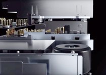
Some of my considerations, looking at the internal picture of UDP 205...
Most likely for this model it will work to connect together the stereo DAC output channels, using the headphone channels too, if this stage it will not be used. It seems Oppo was listening to the critics of wasting two of DAC channels for headphone outputs.
The headphone out in 205 it have its own mute relay, so the switching amp - headphone is made in other way than using the DAC mute function, and hopefully the digital volume control it may be common. I`m very optimistic about this modification potential.
Another observation is that this model it have three analogue power rails, and it looks to me that two of these rails it may be used to power the DAC chips, for their digital and analogue stages. If so, then it is a progress even over Sonica DAC, which it used the old Oppo analogue power design approach.
I can see two 1117 regulators of a new generation (maybe), and I assume these are used for digital stage of the DACs, while the ADM7151 are used most likely for the DACs analogue stage (also as in Sonica DAC design). It looks to me that Oppo still power the clock from DAC`s AVCC rail.
A more sophisticated headphone stage output, based on the same TPA6120A chip (which is a very good amp, BTW), followed by most likely an complementary transistors stage, This it can provide both very good quality, as a lot of power for driving very well the lowest impedance headphones. I think I will prefer this output as line out, rather than the standard RCA out...
Even it may looks like not so important, I appreciate the way the mute relays are more convenient and logical positioned in this new model, to shorten the signal paths and maybe for a better shielding, or better noise figures. However, the same AC coupling approach, using bipolar caps insted of the right ones...
I see the toroid is not shielded as in previous models, for sure to lower the production costs (quite sophisticated mechanical mounting for the previous models, which indeed it not offered any practical advantage, but only unnecessary loaded the production costs). As this toroid is less powerful than the previous ones, and well placed, it may not necessary need an magnetic shield, but I still think it should be damping mounted on chassis, especially for this 205, when is no more encapsulated.
I still appreciate as insufficient the filtering capacities for analogue power rails.
As before much improving potential for this model too, even thought it may be less modifications, for a even more quality increasing, comparing with the previous devices...
Last edited:
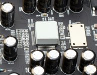
Ceramic chip on top of ESS9038 chip is acting as heat sink. The 9038 runs really hot so a big piece of ceramic (mounted with heat sink compound....yes, you can remove the "hat") helps keep it cool.
The 9038 is four 9028s in parallel. It runs 4 times as much current and has four times less output impedance (200 ohms per DAC pin).....or 50 ohms with all four in parallel.
Sonica DAC smokes all Oppo products before it. With the low noise power supplies, 9038 DAC chip, better clocking, Elna caps, etc. they are using, Oppo has upped the game tremendously. The Sonica (with mods, of course).....is way, way out there. The 205 should be nearly as good....especially if you parallel all the outputs on the DAC and go with super output stage. Any further modding of Oppos without the 9038 chip is simply a waste of time. The new chips and power supplies are so much better......old DAC chip sounds really veiled! Please sing along.....Who wants yesterdays DAC chip?, who wants yesterdays Oppo?.....nobody in the world.
Fun stuff....of course, there is the LKS DAC with two 9038s in parallel (a world's first?).....that is equal to 32 9028 channels......25 ohms output impedance....yikes. It also has heatsinks on the 9038s but are the usual aluminum.
From what I can see (and also having a Sonica DAC here) the 205 power tranny has three outputs because they are using a separate winding for the low voltage regs/clock on the multichannel board. The 12V regulator on the big heatsink is used as pre reg for all the low noise 3.3 volt regs on the all the DACs (I do believe). This is exactly the same as Sonica.
Last edited:
Hi Ric
Many thanks for your intervention and always pertinent observations/informations.
Indeed this is the only logical explanation of that hat, acting as a heatsink. But why ceramic and not aluminium? Much better and efficient is the usual aluminium heatsink, with a much bigger air contact area... However, a ceramic brick it is cheaper than a such aluminium heatsink, or maybe there is about a kind of aluminium compound there, which it may look like ceramic... Well, we shall see soon. I fully agree that cooling the DAC chip is a good thing. I have applied already an improved cooling to the ESS9018 in my mods.
Indeed,there is the same design for both Sonica and 205 DAC stages. I suspect the 205 design is a little bit more evolved, and this it may corroborate with the fact that 205 it came the last one in the new Oppo product series.
I can agree with the supposition that two of the toroid winding are designated to the two DAC power rails (stereo and multi-channel).
As there is the same design used in both Sonica and 205, the last device it have the advantage of a much more complete media product, than Sonica (only DAC). Personally I may opt for 205...
Had you yet the opportunity to take a look under the clock shielding? I wonder very much what it may be there... What kind of clock they use this time?
Last edited:
I think I have a possible answer about why ceramic and not aluminium heatsink... If this heatsink it may disclose from the chip for some reasons, then it will not produce catastrophic damages (shorting) inside... For sure, a safety mounting of a usual heatsink over the DAC chip, is much more costly for production line, than only gluing there a ceramic brick...
Well, the specialists says a ceramic made heatsink it may be more efficient than a metal made one...
So, there is no mystery longer in this area... However, I would like a better approach in place when about cooling the DAC chip. That brick is enough far from a proper efficiency...
So, there is no mystery longer in this area... However, I would like a better approach in place when about cooling the DAC chip. That brick is enough far from a proper efficiency...
Something about the Oppo`s conceptual design for the new 205 model:
https://www.oppodigital.com/KnowledgeBase.aspx?KBID=129
They implemented the SAW oscillator in their new model (thanks to Joe Rasmussen...), and adopted the concept of a master clock for different stages into the device system (thanks to Coris...). Not bad, isn`t it?
BTW, the SAWs I use for quite a time ago, are Epson custom produced too...
Last edited:
https://www.oppodigital.com/KnowledgeBase.aspx?KBID=129
They implemented the SAW oscillator in their new model (thanks to Joe Rasmussen...), and adopted the concept of a master clock for different stages into the device system (thanks to Coris...).
True. Not having seen a 203 yet, this is about the HDMI outs only? Looks like it, to help receiving end (at the other end of HDMI cable) to reconstruct clock signal. So under the board did you spot a 148.5 MHz SAW clock? I would suspect near HDMI outs?
BTW, the SAWs I use for quite a time ago, are Epson custom produced too...
Remember somebody beat you to it?
I had some 54MHz made by Epson and I spotted the SAW for the reason that Oppo now highlight as well, that the SAW oscillator is a 'fundamental' oscillator and not 'harmonic' and wondered why nobody had used them as it looked like it is fundamentally (pun intended) a more stable way of getting a clock signal.
To quote Oppo:
"SAW is able to produce high frequencies with fundamental mode oscillation only, resulting in a clean clock source with no spurs and does not exhibit frequency jumps. It does not require PLLs to achieve the 148.5 MHz output. SAW has ultra-low jitter and excellent phase noise performance. The long term stability and reliability of SAW are far better than a crystal oscillator at the same 148.5 MHz frequency since the crystal tuning fork will be too thin to be reliable. The SAW oscillator clock source ensures that the UDP-205 has the best possible clock signal for HDMI audio."
So yeah, with 148.5MHz being such a high clock frequency, SAW would be the natural choice.
Of course, SAWs are not a great option with older DACs as their clocks are generally too low in frequency. So when the Sabre DAC came out, that was a game changer and I pounced on that. And then I also realised I could get a SAW divider working for 50MHz=25MHz and later 54MHz=27MHz. And Epson and Megacoal were obliging.
Now manufacturers should get onto this too - not just what looks like a HDMI solution only (unless I got something wrong?) and it is time get away from harmonic clocks. Go fundamental.
.
True. Not having seen a 203 yet, this is about the HDMI outs only? Looks like it, to help receiving end (at the other end of HDMI cable) to reconstruct clock signal. So under the board did you spot a 148.5 MHz SAW clock? I would suspect near HDMI outs?
203 model does not use this HDMI approach described by Oppo in their papers. This 148,5 Mhz clocking is particularly implemented to 205, and it is indeed a step forward.
203 it use the same old approach: a 27Mhz resonator driving the processor`s inside clock circuits.
Improving the clock for digital streams inside the system it have of course positive impact over the DACs and audio signals quality, outputted form the both analogue sections of the player...
Little by little, step by step, the mods for Oppo players it become fewer and fewer...
/ Already ordered my 205...
Last edited:
Hi Coris
Yes, you are right, this is about the '205 being the 'sound premium' choice over the '203 and fixing something that improves sound via HDMI.
I saw an earlier pic of yours on the '203 and your battery(?) powered clock(s) and you drive the 27MHz underneath, but also another one. Is that 25MHz and your opinion on the 25MHz's job?
Have you access to ES9038 datasheet? We have them and ES9028 too, but not allowed to spread them or post them. But our 'group' was able to get them. I think Ric might also have it.
The output impedance is 202 Ohm for the 9038 and 806 Ohm for the 9028, so Ric looks to be right, the have paralleled up outputs in the 9038. Analog Current 1.2V 128mA + 3.3V 90mA versus 82mA 1.2V + 3.3V 47mA, so that explains why 9038 runs quite a bit warmer.
.
Indeed, the second (well, there is a third one, but that is for USB section) oscillator in 203 is 25Mhz. This one it drive the processor beside, and it seems to me to be a kind of all in one decoder for the data outputted by the UHD drive (there are streams from CD, BD/SACD, and UHD discs), which it have to be processed somehow before getting into the main processor. As the UHD streams are huge, comparing with the rest of discs standards, a stand alone processor it may do the job. Well, this is my interpretation, which it may be corrected, if someone have more precise informations about this field.
So, the 25Mhz oscillator it have impact first over the picture quality for UHD playback, as for audio digital coming from discs playback. This oscillator it should be a good one, as good as the one for processor, or better...
I use both, a SAW divided to 27Mhz and another very good oscillator for 25Mhz on my clock board (battery powered), providing so the clocks for the 203 model.
Yes, I have now the datasheet of the ESS9038Pro. It is spread it already, and accessible, after a little bit searching.
Indeed the new chip it use more power, and this is normal. I would like to point that the 128mA current for the digital core (1,2v), is specified for a 40Mhz clock. Why so, when this frequency is not usual at all, may ESS answer... However, they never answer to anything...
This current for digital core it may increase quite much if a 100Mhz clock is used, as correlated with the digital content to be converted. I presume we should expect there a current of into 300mA or even more. At least a capable regulator for 500mA should be a right choice, or expected to be used in this place.
The same digital core (VDD 1,2v) in ESS9018 is specified in datasheet for 37mA, but this is not just right in fact. This current it is in mute status around 60mA. In standby (no playback/conversions) is 80mA, and it can increase up to 150mA, function the data to be converted. We can expect a similar behaviour about the new chip too. So, one should be prepared with an enough powerful regulator for this rail...
The heat dissipation on the new chip is also enough high, for such hundreds of mA which it goes through... I doubt already about the efficiency of that ceramic brick (heatsink)...
Last edited:
...high resolution audio music for example tidal or Spotify
I am considering Tidal soon, if it can be done for the Sonica, it should be able in '205 too or very odd if not.
Coris has a '203, maybe he can tell if Tidal is available, if its there, it confirms '205.
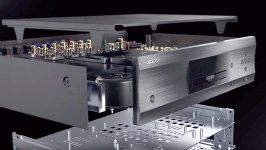
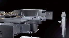
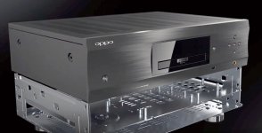
Some more details about the inside of 205 model...
Again the misleading image of the springs under the disc drive, suggesting a elastic suspension. In fact (for this model too) a very rigid drive mounting into the chassis....
Again the misleading image of the springs under the disc drive, suggesting a elastic suspension. In fact (for this model too) a very rigid drive mounting into the chassis....
Attachments
Last edited:
- Home
- Source & Line
- Digital Source
- Oppo new UDP series players - 203/205 - Discussions, upgrades, modifications