Capacitor swaping and opamp rolling is hardly called an "upgrade".
Do some real upgrade work, like fixing digital input, new power supplys for 74VHC153, 74VHC32, 74HCU04, 74HCT14...chips, or adleast isolate them. Get rid of noisy DC-DC switcher inside, make new regulator for clock supply, right now there are ripples over 100mV there
Make new analog section & new power supply for analog section and fix a lot of other things. Been there, done that.
The changes I made are modest compared to the more advanced work you have done but it does sound better than when I bought it, which makes it a mini-upgrade at least!
2 questions:
1) please can you post some details (or weblinks) for the advanced modifications you suggested for the DACMagic Azure?
2) which ones are worth doing for a CE unit like this?
Where is this DC coming from? From preamp coming back to DAC? Then your preamp is faulty.
Mine is fine thank you. But you can see why I suggested hooking up a VM before assuming the output caps aren't needed. Better safe than sorry.
Last edited:
This may be a daft question but is there any way we could reduce the loading on the NE5532's (or their replacements)?
Its not a daft question, but the solution will be quite a bit of rework on the board. There's a fairish number of 0204 Melf resistors to change in order to do this, and there'll be a slight noise penalty (maybe too small to notice).
...is there any way we could reduce the loading on the NE5532's (or their replacements)?
Depending on whether you want the RCA outputs or not, you could remove the OP275s and the 1k input resistors that surround them (R194,R195,R218,R219). This will decrease the loading to about 1k Ohm, but will also disable the RCA outputs.
Alternatively, as mentioned earlier, you could scale the resistors. I would suggest scaling R194,R195,R196,R197,R218,R219,R220,R221 to about 6k8. And then changing R182,R183,R190,R191,R206,R207,R214,R215 to 10k. This will bring the load down to 2k, while keeping the RCA output functionality. Don't bother with the capacitors, 10pF is nothing; I think they are there for yield purposes, just in case the amplifiers have a tendency to oscillate. In fact, the dacmagic might actually sound better with C283,C290,C320,C326 removed.
As for noise, I'm pretty sure the opamps will still determine the noise level.
If anyone does decide to go this way, good luck replacing 16 SMD resistors! I personally prefer replacing 4 dual op-amps.
--
Greetz,
MatchASM
you might want to try the OPA1642 as well, in the same vein as 1612, but better in every way. gotta love jfet input opamps
I thought the OPA2141 was the state-of-the-art in JFET opamps...
Anyhow, I personally dislike JFET sound, and the high input impedance is not strictly needed here, since we're not building a phono preamp. So I would recommend replacing bipolar with bipolar.
But if you're a JFET fan, nothing stopping you from trying any of the OPA627/1642/2134/2141/2604 (or AD823, if you dislike TI).
--
Greetz,
MatchASM

Amended parts list
Hopefully I have corrected my mistakes
1. Replace the output capacitors which are C1/C2 and C40/C41 on the balanced outputs, C293 and C299 on the unbalanced outputs. These are 470uF 16 V, non-polarised electrolytic – I used Michicon Muse ES. Or just short them out by turning the PCB over and soldering a thin wire across each capacitor’s pins. However this DC couples the DACMagic output to the preamp or amp it is plugged into, so consider using a DC voltmeter first to measure the DC offsets on DACMagic and the input you are connecting into.
2. Replace the power supply capacitors for the op amps/analogue circuits. I used Panasonic FC’s as follows:
a. C76, C77, C402, C403 are 1,000uF 50V
b. C414, C415 are 10uF 35V
c. C419 is 1,000uF 35V, I used 1,000uF 50V as 2a above
3. Replace the power supply capacitors for the DSP and DAC digital circuits. I used Rubycon ZA’s and ZLG’s:
a. C424, C425 and C89 are 2,200uF 25V – the first two need to be smaller e.g. ZLG to fit in
b. C87 is 1,000uF 25V, I used 1,000uF 50V as 2a above
c. C8, C10, C25, C26, C31, C35, C45, C130, C426, C431, C435 are 10uF 35V
d. C103 is 100uF 16V
4. Replace the decoupling capacitors around the two WM8740 DAC’s. I used Rubycon ZLG’s:
a. C270, C275, C276 and C301, C303, C304 are all 10uF 35V
b. C271 and C302 are 47uF 35V – I used the DACMagic value and not the 10uF on the WM8740 datasheet
5. Replace the op amps, which are tiny surface mount SO8 packages and on very thin PCB tracks:
a. U55, U56, U59, U60 are NE5532D and can be upgraded to your preference (please see earlier postings about the THD) - I used 4562MA’s
b. U57 and U61 are OP275GS which can be upgraded to 4562MA or your preferred op amps
I left C44, C400 and C401 in place. You can also leave C5 and C212 as they are just the mute/relay supply.
Idea for modification
I don’t use the USB input and could probably use a third 24/96 bit input on the DACMagic. The 16 bit USB suffers from jitter and would need a lot of work to approach the quality of the other 2 inputs. As an alternative why not split the optical and coax input for digital input 1, so optical 1 replaces the USB input? This gives an extra 24 bit input?
In theory (I haven't tried it myself!) the modification would be along the following lines. Cut the underside PCB track from U23 pin pin 8 to U7 pin 5. Cut the track joining optical 1’s R16/C201 to U7 pin 3, connect this to pin 5 instead. Then connect U7 pin 3 to ground. I think these changes separate OPT 1 and COAX 1 so both can be connected.
The photo I posted today shows the basic idea in red. Optical 1* replaces the USB input. If it works, the three switchable inputs become OPT1, COAX1, and OPT2 or COAX2 depending which is connected.
* I think the schematic labelling of inputs 1 and 2 may be the wrong way around. U5 is optical 2 and goes to U7's 1-IN2, similarly for coax in 2 going to 2-IN2.
Last edited:
Depending on whether you want the RCA outputs or not, you could remove the OP275s and the 1k input resistors that surround them (R194,R195,R218,R219). This will decrease the loading to about 1k Ohm, but will also disable the RCA outputs.
Alternatively, as mentioned earlier, you could scale the resistors. I would suggest scaling R194,R195,R196,R197,R218,R219,R220,R221 to about 6k8. And then changing R182,R183,R190,R191,R206,R207,R214,R215 to 10k. This will bring the load down to 2k, while keeping the RCA output functionality. Don't bother with the capacitors, 10pF is nothing; I think they are there for yield purposes, just in case the amplifiers have a tendency to oscillate. In fact, the dacmagic might actually sound better with C283,C290,C320,C326 removed.
As for noise, I'm pretty sure the opamps will still determine the noise level.
If anyone does decide to go this way, good luck replacing 16 SMD resistors! I personally prefer replacing 4 dual op-amps.
--
Greetz,
MatchASM
Thank you for a helpful and thorough answer. And good point about the part change counts!
Last edited:
I don’t use the USB input and could probably use a third 24/96 bit input on the DACMagic. The 16 bit USB suffers from jitter and would need a lot of work to approach the quality of the other 2 inputs. As an alternative why not split the optical and coax input for digital input 1, so optical 1 replaces the USB input? This gives an extra 24 bit input?
Yes.
In theory (I haven't tried it myself!) the modification would be along the following lines. Cut the underside PCB track from U23 pin pin 8 to U7 pin 5. Cut the track joining optical 1’s R16/C201 to U7 pin 3, connect this to pin 5 instead. Then connect U7 pin 3 to ground. I think these changes separate OPT 1 and COAX 1 so both can be connected.
Ok, except I would connect U7 pin 3 to ground through a 100 Ohm resistor, to prevent parasitic oscillations. The mod should work, AFAICT.
--
Greetz,
MatchASM
I assume you're talking about the switching regulator labeled U12 that supplies +5V to the clock and the DSP regs. Is it worth replacing it with a linear regulator? I've got a spare SOIC-8 Browndog just for the occasion...Get rid of noisy DC-DC switcher inside, make new regulator for clock supply, right now there are ripples over 100mV there
On an unrelated note, I've installed Dexa regulators in the analogue supply and replaced remaining Xunda electrolytics with Panasonic FC/FM. The result is a major improvement in clarity, and perhaps the soundstage is a bit wider.
@gtx580m
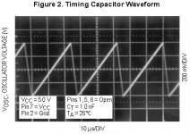
Look at MC34063 datasheet. What is output ripple with optional filter?
Yes, "only" 40 mV in datasheet, but in real world there is over 100 mV ripple at clock and DAC chips.
You can play games with timing capacitor value & change frequency, but noise from MC34063 will be everywere. If your ears are good enough, you can hear L1 whistling with high tone
Attachments
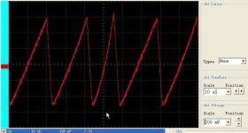
Indeed I can, though the whistling fades out once the unit finishes booting. I thought that was due to loose inductor casing.If your ears are good enough, you can hear L1 whistling with high tone
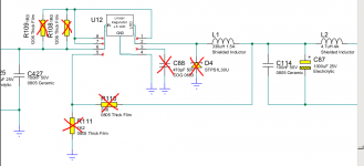
Alright, a newbie question. Will this work (see attached pic)? Crossed out elements are to be desoldered; U12 pins 1, 3, 5, 7 and 8 are left open.
Attachments
Indeed I can, though the whistling fades out once the unit finishes booting. I thought that was due to loose inductor casing.
Alright, a newbie question. Will this work (see attached pic)? Crossed out elements are to be desoldered; U12 pins 1, 3, 5, 7 and 8 are left open.
If it was so simply CA has made so
. But thermal emissions in that case make approximately 0.190 A x (16.5 - 5) V=2.185 W. To be necessary enough big heat sink for the linear regulator and where you will put it? And all it will be heated nevertheless.Yes, Mihaylov, you are right. Whole power supply is a mess
I wrote few posts back that there is a long way to fix things inside Dacmagic.
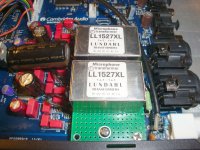
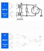
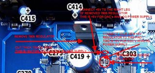
Bellow is picture how to connect two new +5V regulators for WM8740 digital & analog part.
I wrote few posts back that there is a long way to fix things inside Dacmagic.
Bellow is picture how to connect two new +5V regulators for WM8740 digital & analog part.
Attachments
Last edited:
Ideally we would have separately regulated supplies to the crystal/masterclock, the DSP, and the digital sections of each DAC. Plus separate low noise regulated supplies to each DAC's analogue circuits. So six 5V supplies and separate low noise regulated +/- 15V for each channel's op amps. It's a small warm box now and an external box would be needed for the supply circuits, as suggested on the previous page.
The existing power supplies are a compromise between space, heat and parts count/cost. Comparing to the power supply schematics for the CA740C and CA640C, shows what's been left out! But to be fair the DACMagic works reasonably well.
Retrofitting the extra supplies means a fair bit of PCB track cutting would be needed to split the connections to the different IC's. And some strain relief on the cables to an external PSU box.
We could make a smaller scale modification to the power supplies. There is dedicated 5V supply for the USB circuits with a 7805 regulator. If we disconnect the USB and put a heatsink on this 7805, could it be used for some of the digital circuits instead of the DC-DC convertor and its whistling inductor?
Last edited:
- Home
- Source & Line
- Digital Line Level
- Opening the new DacMagic????