New analog board planned
I'm planning a new analog board upgrade. It's anmed AB-1.12. Here's what I'm planning to do.
The board will be made available as a naked board compatible with today's USB-I2S module. I'm not planning to make it into an unassembled kit with lots of loose components. The 22.5792 XO may be hard to come by. I have a bunch of those coming in in what will probably be mid-March.
1 - Remove ES9023, install PCM5102. The working principle is much the same with internal charge pump and single-ended supply in.
2 - Add footprint for ES9012/18. But only the SMD parts. Any PSU and IVC will have to be installed by you. And obtaining the DAC is also up to you. All headers will be on the same 2.54mm / 100mil grid for easy veroboarding. I'll put in footprints for dual-mono.
3 - Add footprint for CS8406 S/PDIF transmitter and transformer. This is a I2C controllable transmitter, so some fw updates will be required. I'll make room for an S/PDIF output connector on the front, opposite the LED. One thing this will allow is recording of the S/PDIF signal for offline analysis of bit-correctness.
4 - Add I2S CAT5 header at the front. I'll need more input from you on preferred pinouts. I was planning to install simple 74HC series drivers on 3.3V supply with series resistors in and out of the buffer.
5 - New front/back covers. I'll remove metal from around the connector holes, and add metal around the srews bor better connection to the case. The front cover will come with or without holes for the new S/PDIF and CAT5 outputs. The new covers will be red, indicating AB-1.1_2_.
It'll take me a little while to put all this together in the CAD. I'll show you schematics and layout drafts in good time before I get the boards made.
Let me know if you have any more (reasonable) suggestions, and if you'd like to get a board. I'll get back with price info in a bit.
Cheers,
Børge
Hi Borge,
The github sdr-widget audio-widget-nik branch has the latest code tree.
The main difference that I can see is that I build with the X86_64 linux toolchain, and you use Windows 32 bit.
My conjecture is that the x86_64 linux toolchain produces more optimized code (I hope, hihi) than Windows. You can also see that my .elf files are much smaller than your .elf files. It is likely (but I have no proof) that under Windows, you may be compiling with debug options on - thus the bloated .elf files. Maybe a Windows AVR expert can advise how to set build options for highest execution speed and no debug.
As the audio-widget code is running almost at the limits of the cpu power of the AT32UC3A3 chip, any suboptimized code (and extra debug baggage) will surely cause underruns/overruns in the audio code --> poor SQ.
Alex
I'm planning a new analog board upgrade. It's anmed AB-1.12. Here's what I'm planning to do.
...
It'll take me a little while to put all this together in the CAD. I'll show you schematics and layout drafts in good time before I get the boards made.
Let me know if you have any more (reasonable) suggestions, and if you'd like to get a board. I'll get back with price info in a bit.
Cheers,
Børge
Hi Børge.
Why not add the regulator board suggested by 1audio and tested by oneoclock? At least settle for a set of connectors so it can be added easily afterwards.
I am interested in one AB1.12 analog board.
Brgds
Thanks for the link, but I think that paper has a few flaws.I have read through the paper on the J-test signal at http://www.nanophon.com/audio/diagnose.pdf
What strikes me is that this input signal is designed to fool a clock regenerator / AES3 receiver to generate its maximum amount of jitter. This is done by transmitting what is essentially the same fs/4 signal with mainly zeros or with mainly ones. A full cycle of zeros... ones... has a frequency of fs/192.
As far as I can interpret the paper, this signal only applies when the performance of the clocking circuit depends on the actual data bits. In the Audio Widget the clock stems from precision oscillators, not from an AES3 or S/PDIF receiver.
Thus, for jitter purposes, we might as well study the frequency-domain response of a pure tone as the J-test signal.
1) The square wave test signal described in 2.6 seems completely devoid of band-limiting, which means that it contains aliased signals. You cannot simply create a square wave in data unless you take steps to avoid aliasing. The proper way to generate a square wave is via summing the harmonics as pure sine waves, thus guaranteeing that no aliasing is created. I suppose it's possible that the test signal also corresponds to a pure sine wave with a period of 4 samples and a phase offset of 45 degrees (pi/4 radians), but then it's a bit misleading to call it a square wave.
2) The text in 2.6 seems to overlook the characteristic of AES3 where the preamble always starts with the opposite bit from the preceding sample. The last bit of each word is the parity bit, which means the preamble is modulated by the parity of the data stream. Parity includes more than just the audio data - it also includes the validity bit, user data, and channel status. I suppose it's possible that by carefully controlling the audio samples and zeroing out the user data, one could predict the parity. However, valid channel data would introduce a pattern that would affect parity, and thus affect the preamble pattern. The authors' characterization of the preamble as a "static, and therefore more stable, pattern" is completely wrong. At the very least, they do not explain enough details to prove that they have done anything to make the preamble static. What's more, that section of the text seems to refer to general designs for clock recovery which are expected to work with musical audio rather than just test signals, and as such there is absolutely no guarantee that the preamble is static at all.
One of the first dark and dirty secrets I learned about AES3 is that this bit flipping of the preamble causes nightmares for engineers trying to reconstruct a stable clock. To read the opposite in this article really strikes me as a sign that suspicion should be warranted for all of their claims. It would not be the first time that a published AES article was flawed - in fact, many published AES articles are refutations of flawed claims in previous AES articles!
Anyway, to get back to your closing remark, Borges, I agree with you. A pure tone will vary the parity bit, thereby varying the preamble, and thus varying the selection between rising and falling edges at the start of each sample word in the digital audio stream. This should be enough to challenge any jitter recovery system - at least in a way that matches normal use.
Note that some AES3 transmitter hardware violates the specification by only using one set of preamble patterns, thus allowing a DC offset in the stream. I do not know how common this flaw is, but some processor chips that implement an AES compatible serial port use this trick to reduce their silicon cost, with no regard for the full specification.
Note also that I have no direct experience with the task of trying to create the worst jitter possible. I think the linked article was a noble effect, especially given the time (1994), but I only point out the errors without providing the 'correct' test pattern.
I have been to AES meetings where local engineers (Mackie, Rane, etc.) demonstrated methods for introducing jitter into a digital audio stream. My recollection is that they merely mixed analog white noise into the digital stream to create the jitter. They used pure tones and a spectrum analyzer on the DAC output, and it was very clear (visibly) when they turned their "jitter generator" on and off.
Finally, you are quite correct that the Audio Widget is very different from a digital audio stream receiver. The Audio Widget generates its own clock and forces the USB Host to slave to the Audio Widget clock using the rate feedback endpoint. There's no way to alter the clock by changing software on the USB Host or even by adding noise on the USB lines. What's probably necessary to introduce jitter on the Audio Widget would be to probe the traces or parts pins in a way to introduce noise in the clock lines. Of course, there are many other ways to screw up the clock, but it would not be data related as with AES3, because clock is not carried with the data for USB Audio.
Thanks 1Audio. I hope these improvements for enhanced board.
If few people who want this board and are satisfied with my poor quality board I can make and send free to those who are collaborating.
I make board at home with low quality bakelite, laser printer paper and revealed copper at home.
I do not know where to order plates and I doubt I can get a good price for that.
Borges, AB1.12 new board looks very interesting analog options
Could you include two 1Audio source boards without components?
Borges, AB1.12 new board looks very interesting analog options
Could you include two 1Audio source boards without components?
Sure, if Demian doesn't mind.
For PCB manufacturing let me suggest PCBcart. You'll have to supply Gerber data, though.
Børge
Hi Borge,
The github sdr-widget audio-widget-nik branch has the latest code tree.
The main difference that I can see is that I build with the X86_64 linux toolchain, and you use Windows 32 bit.
My conjecture is that the x86_64 linux toolchain produces more optimized code (I hope, hihi) than Windows. You can also see that my .elf files are much smaller than your .elf files. It is likely (but I have no proof) that under Windows, you may be compiling with debug options on - thus the bloated .elf files. Maybe a Windows AVR expert can advise how to set build options for highest execution speed and no debug.
As the audio-widget code is running almost at the limits of the cpu power of the AT32UC3A3 chip, any suboptimized code (and extra debug baggage) will surely cause underruns/overruns in the audio code --> poor SQ.
Alex
I reprogrammed my AB-1.1 last evening and suddenly got heavy distortion in the middle of songs. They lasts about 15-20s but there between the sound is great.
My widget controls are as they should for WindowsXP:
usbi2s, uac1_audio, normal, normal, none, es9022, none, 500ms (or 1s - can't remember).
I will test what Georges board gives since I reprogrammed it on the fly when at it...
Brgds
I never had a chance to listen to AB1.0, but also I have noticed a sensible improvement between the (old) stock firmware and the latest ones. Thus I definitely second your advice.This morning I updated the AB1.1 with the latest nik branch firmware and voila, the SQ improved significantly and is now on par with my AB1.0.
Yet what puzzle me is: why?
(and: what happen if you update your old AB1.0 to the latest firmware? does it also improve gettin' again better than 1.1?)
OK, Georges unaltered board has the same sudden distortion a bit in to the songs and my feeling is as someone decided to increase the input voltage fast and to much - heavy clipping... But only on some frequencies is my feeling.
In Black Sabbath 1970 24/96 ripped from vinyl Paranoid-Ironman the song seemed to be quite unaltered at times when distortion sat in but the rest of the instruments sounded as crap... The suddenly, everything is fine again???
Still WinXP
My widgetcontrol values:usbdac, uac1_audio, normal, normal, none, es9022, none, 1s
BTW: I noticed that the LEDs are not blinking when playing? New feature?
Brgds
Last edited:
I see that some of you have distortion problems running uac1 under Windows.
I have tweaked the uac1 rate feedback param. New firmware is:
audio-widget-nik-2012-01-15.elf - sdr-widget - Unified firmware for audio-wdgets. Tweaked uac1_audio FB_RATE_DELTA param. - Audio and Control Interface for Amateur Radio SDR and Audiophile USB-DAC - Google Project Hosting
Note that you will need to use WidgetControl to make sure your settings are appropriate for your widget.
Please test and revert")
Alex
I have tweaked the uac1 rate feedback param. New firmware is:
audio-widget-nik-2012-01-15.elf - sdr-widget - Unified firmware for audio-wdgets. Tweaked uac1_audio FB_RATE_DELTA param. - Audio and Control Interface for Amateur Radio SDR and Audiophile USB-DAC - Google Project Hosting
Note that you will need to use WidgetControl to make sure your settings are appropriate for your widget.
Please test and revert
Alex
Thanks Alex,
could you please post your toolchain setup so that I can replicate it on my Ubuntu 11.10 installation? If make-widget-win7 doesn't cut it we must fix it or remove it. In any case there must be a known good way of building the fw.
A wiki page might be in place.
Børge
could you please post your toolchain setup so that I can replicate it on my Ubuntu 11.10 installation? If make-widget-win7 doesn't cut it we must fix it or remove it. In any case there must be a known good way of building the fw.
A wiki page might be in place.
Børge
I see that some of you have distortion problems running uac1 under Windows.
I have tweaked the uac1 rate feedback param. New firmware is:
audio-widget-nik-2012-01-15.elf - sdr-widget - Unified firmware for audio-wdgets. Tweaked uac1_audio FB_RATE_DELTA param. - Audio and Control Interface for Amateur Radio SDR and Audiophile USB-DAC - Google Project Hosting
Note that you will need to use WidgetControl to make sure your settings are appropriate for your widget.
Please test and revert
Alex
Hi,
something is wrong if I playback hi-res files (24/96) with mpd and the widget/AB1.1 It sounds like having way to much treble energy.
Using it with sox in a pipe arrangement (processing phono input) sounds just fine (in 24/96, again).
16/44.1 is fine via mpd, as well.
All in linux 2.6.39-gentoo-r3
Im a missing something fundamental?
Here is my mininmal conf example:
Rüdiger
something is wrong if I playback hi-res files (24/96) with mpd and the widget/AB1.1 It sounds like having way to much treble energy.
Using it with sox in a pipe arrangement (processing phono input) sounds just fine (in 24/96, again).
16/44.1 is fine via mpd, as well.
All in linux 2.6.39-gentoo-r3
Im a missing something fundamental?
Here is my mininmal conf example:
Code:
audio_output {
	type		"alsa"
	name		"Musik-Server (ALSA, USB)"
	device		"hw:1,0"
Rüdiger
We really need some sort of sample-by-sample analysis
Any experience in bit-correct SPDIF recording to file? If that is doable, an SPDIF output may be a good analysis tool.
Børge
Its relatively easy to capture an SPDIF output with a decent sound card. Accurate capture is not a problem and the format has proven very reliable. I suspect you won't find anything interesting.
You could get a demo board for an SPDIF transmitter and patch the I2S lines into it, easier and quicker than making a board. However there is a lot of interest in an SPDIF output anyway. The board could easily support SPDIF or AES/EBU and conversion is done with resistor values etc.
I would suggest that you use the PS Audio originated I2S interface over HDMI instead of the RJ45. Its getting more traction and has the benefit of differential high speed connections. They did not support remote clocks but we could add that as an option. It seems it only needs one chip. I have the pinout somewhere in my collection.
If there are available gpio pins on the module I would like a sample rate indication. A bit depth indication would be great, however that is not so simple.
Hi Rudiger,
You are missing the command to turn autoresampe OFF
So what your were hearing was resampled sound. Of course it is not so good
See my .mpdconf below:
alex@alex-Aspire-4750:~$ cat .mpdconf
port "6600"
music_directory "~/Music"
playlist_directory "~/.mpd/playlists"
db_file "~/.mpd/mpd.db"
log_file "~/.mpd/mpd.log"
audio_output {
type "alsa"
name "ALSA Device #1"
device "hw:1,0" # optional
auto_resample "no"
# format "88200:24:2" # optional
}
zeroconf_enabled "yes"
zeroconf_name "alex Aspire 4750 music player daemon"
#samplerate_converter "SRC_SINC_BEST_QUALITY"
Alex
Hi Borge,
To build under Linux, you need first to download the avr32 toolchain from Atmel.
Then you modify the make-widget file to set the PATH to the correct place of the toolchain (depending on where you download it to).
Mine is below. So your should probably modify the directory to /home/borge/.....
#!/bin/sh
##
## this makes the widget if the AVR32BIN environment variable
## is pointing to the directory containing avr32-gcc
##
PATH=${AVR32BIN:=/home/alex/as4e-ide/plugins/com.atmel.avr.toolchains.linux.x86_64_3.1.0.201012011657/os/linux/x86_64/bin}:$PATH
export PATH
cd Release && make all
Once the above is done, all you have to do is to type:
$ make
Alex
Sure, if Demian doesn't mind.
For PCB manufacturing let me suggest PCBcart. You'll have to supply Gerber data, though.
Børge
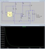
Feel free to use the circuit. We need to add a protection diode between the base and emitter of the sensing transistor. If that transistor is reverse biased to hard its noise will increase, just want we don't want.
I tried simulating with the LT1431 model. Its picky and wants to oscillate if the cap across it is less than 25 uF. I have not seen that on the boards with the TI431 but maybe its a difference in the parts.
I have attached my LTSpice simulation and a picture showing where the diode goes.
Attachments
- Home
- Source & Line
- Digital Source
- Open-source USB interface: Audio Widget