Not much treble getting past C2 !
1000R and 1n5 is 100kHz, is it not? How much higher would you like to go?
And, incidentally, a few volts will probably get scraped off that +-26V with a regulated supply. That would allow using an OPA604.
Christian, was this :
Circuit a bit unstable without all that filtering on the input of the opamp?
Working on the PCB bias and current amplifier part...
No, not at all.
The 100pF is there just to take out RF, and is a pretty standard inclusion (though not the perfect way to do it, which would have a balanced i/p and you can then attack common mode and other separately). The 1k and 1.5nF is just to make sure the amp (power) isn't handed anything it can't correct. No one can complain (apart from Andrew
") , that a 100k b/w isn't wide enough. And the 10uF and 18k (if it's there- I can't see from here) is somewhere around 1Hz, IIRC, so no one can really have an issue with losing too much there.
, that a 100k b/w isn't wide enough. And the 10uF and 18k (if it's there- I can't see from here) is somewhere around 1Hz, IIRC, so no one can really have an issue with losing too much there.@Andrew, the inputs aren't imbalanced. They're both at around 1k. You can check the offset if you like, but it'll be pretty titchy on a FET input like the 604 - or indeed any modern op amp.
Mikhus,
The way to do the op amp is to do what I said above on a strip board; 3 ground and 2 rail strips. You put an LM317 on one side and a 337 on the other (I think one goes in backwards, IIRC) and the resistors and diodes go right next to the components, apart from the Adj resistor and the capacitor it has got in parallel, which go to your local ground. THAT, is the ground you use for your op amp. And it goes back, at the lowest resistance possible, to your main star ground. I would put this close to the o/p end of the op amp, in case you end up using a second op amp.
Get out a bit of veroboard and you will see how it's done.
I like to run my wires for + and - underneath the op amp, but that is a preference of mine. The bypass caps (and I think you should make space for at least two on each rail, (plus one going across the amp from + to -) can either go to this same ground or directly to a ground plane under the chip(s) that comes in as a star to this local ground.
The filter components go to ground, too. Ideally they'll get there will minimum R, but that doesn't matter for the main load resistor or the R that discharges the input cap since they'll hardly notice a miniscule addition to their value.
PS. See if you can find a picture of a tiny little amp that I put up here about a year and a few (3?) months ago. That will have a lot of guidelines as to how to do the layout on it.
Last edited:
Just for clarity, C4 (which I have put in as 150pF, not 100, though either will do) goes directly across the inputs, not to ground, even though it's shown as that on the schematic. (It would usually be put at or near the input socket.) It's supposed to be saying that no RF gets into the box, which is wishful thinking. More effective barriers would have RCs to ground on both sides as well, but that's really for an altogether better input. This is pretty good for what it is.
All of that input filtering is optional, and you can put it in increments if you like, but you will find that it does make things better. But I expect that, to begin with, you just want it to work!
The 1Meg resistor can be anything between that value and as little as 100k (tho' that will affect the input impedance). But 470k or anything you have to hand will be just fine. As I said, it's just there to discharge the 10uF input cap.
It also occurs to me that it might be worth putting 47R on the output of the op amp. It's probably not needed on the same board, but it is not a bad idea in principle. There might even be an argument for putting 47R into In+ as well.
Last edited:
Supply rails as close together as possible... somekind of star grounding...
Sleepy and a bit drunk, that yellow line from from place should be at right place, opamps output... its shielded only from opamp ground and theres no ground connection on current amplification part... as it would cause ground loop...
fotos kostenlos
An externally hosted image should be here but it was not working when we last tested it.
Sleepy and a bit drunk, that yellow line from from place should be at right place, opamps output... its shielded only from opamp ground and theres no ground connection on current amplification part... as it would cause ground loop...
An externally hosted image should be here but it was not working when we last tested it.
fotos kostenlos
Last edited:
M, when I get a moment I will sketch out the way I would do this. But that is quite a bit of work and I don't have a scanner at home.
Funnily enough, I think the straight lines might make things easier to see. But that's sort of the idea. The bypass caps should be right next to the terminals on the chip, and one of the two on each side will be an smd ceramic, the other probably a tantalum - and a tant going across the two maybe. (But I still haven't looked at the datasheet of the op amp.)
i don't really see the power supply (for the op amp) there, but let me get a moment and I'll come back to you with some sort framework - not to say that this won't work.
Incidentally, go and look at some pictures of how other people have laid out their amplifiers. For the power amp part, the A&R A60 is an example of an intelligent layout, but the same can't be said of its pre-amp part (well certainly in regard to where the power supply is). Dismiss any amp that doesn't have symmetry, or its alternative, repetition. Try Krell perhaps (tho' I haven't looked), but ignore Naim as it will not enlighten you, though it might perhaps on the 500, though I doubt it. Rotel might be a good idea too, from the Stan Curtis era and maybe even Doug Self's Audiolab 800 (though I doubt you'll find a regulator in there).
All of those will be instructive and you'll see what other people do.
Last edited:
Reading reports from builders most seem to end up with RF RC from 0.2us to 1us............No one can complain (apart from Andrew
I happen to prefer 0.7us in that I cannot hear any treble loss.
I see 1k1//22k and 18k on the inputs.@Andrew, the inputs aren't imbalanced. They're both at around 1k. You can check the offset if you like,...............
Member
Joined 2009
Paid Member
I'm used to seeing a capacitor across the Vbe multiplier - to ensure it has very low impedance at a.c. - something around 22uFmight be enough.
Why do the drivers have separate emitter resistors (they're gonna get warm) - looks like the emitter loads are therefore limited to 1k at most. If you connect the driver emitters to each other via a current limiting resistor each driver will act as a load for the other but with higher impedance than 1k - and this will increase their linearity.
Do you have rail fuses in there somewhere ?
An output inductor ?
I might also include a capacitor in the feedback shunt, i.e. in series with R8 in post #98. It's there as an option, you can always install a wire link if not wanted. Size the pads for something around 100uF Bipolar 16V.
The other change I might consider is bootstrapping the drivers. Take R13 and split it into two resistors of 4k7 each, connect a capacitor from their mid point to the output of the amplifier (e.g. 100uF 35V). Do the same for R14. It will improve the overall circuit.
Last edited:
I'm used to seeing a capacitor across the Vbe multiplier - to ensure it has very low impedance at a.c. - something around 22uF might be enough.
Why do the drivers have separate emmiter resistors (they're gonna get warm) - looks like the emitter loads are therefore limited to 1k at most. If you connect the driver emitters to each other via a current limiting resistor each driver will act as a load for the other but with higher impedance than 1k - and this will increase their linearity.
Do you have rail fuses in there somewhere ?
Yes, you're quite right on the capacitor. I had noticed that a number of times, but each time forgot to mention it as an omission. Perhaps because it's a tricky component to know how to choose the value. Anything from 4u7 upwards would appear to be OK. I have actually never looked carefully at what effects the values have, but it also has a role in making sure the bias stays stable. In fact, that's always the role I've seen for it, rather than a free ride for AC, though the two might turn out to be complementary.
As for the drivers, I just thought this was simple and in line with the Class A potential that Mikhus wanted to have. There must be a dozen ways of doing them but I didn't have Cordell's book to hand and, from memory, the best that he has gets to be quite complicated, which is not the idea here. (Do bear in mind it was just a reply to a thread!
) Sure they'll get warm, 25 mA or nearby, I think, but they will stay at the same temp. I take your point, though I'm not sure it will increase their linearity. They are there to have sufficient quiescent to be absolutely sure of driving the bases of a paralleled output. Anyway I like things to be determined rather than left to the vagaries of transconductance - not for any particular reason, but it's nice to be able to put figures where we can. Also, not that it's especially relevant here, I tend to be naturally against active loads and that preference may have had an influence in my preferring just a resistor.Fuses? Who needs fuses?
@Bigun
Taking a second look, that's a really interesting point on the linearity. For the moment I'll stick by it not making a difference (or only a smidgeon). 1k at 25 or 30mA should be all the linearisation one needs.
But the dominant load will, in any case, be what it sees at the base of the power transistor. And that is a reflection of the loudspeaker. It could be as little as something varying around 900 Ohms. It looks to me like a very good argument for a cfp output.
I can't see that this problem gets better with what is effectively more degeneration, but I can see why one might want to be tempted by it. If everything is lovely and benign, then it looks better, but I'm not sure we ever realise that in practice. But I'm certainly happy to turn that over to your views.
@Bigun, again
I'm sorry. I didn't see the second half of your post for some reason.
Output inductor? Yes, that would be my choice.
Cap? I was rather expecting it wouldn't be needed (and still do) though I'm sure it crossed my mind in an earlier post. I think in that post I might have asked for a place to be left for a small stopper resistor, just in case. (But that may be somewhere else.)
Sorry, now that I see you're asking to be able to short it, I realise it's not that capacitor.
So, unity limiting cap to ground. Possibly my least favourite component in an amplifier! Yup, it may be needed, but I rebel against every aspect of it. It screws up the proper transfer function of the high pass that it is supposed to be, and all those with it, because it doesn't go to zero; it is in the feedback circuit so has a direct influence on whatever comes out of the amplifier; it gives a very tenuous connection to what is supposed to be our reference ground. It's shitty all round. It may be a good idea to leave a place for it, but I do wonder why one bothers.
R13/14 are for the Vbe multiplier. I am trying to persuade Mihkus that this and the op amp input should both be regulated. Ie. a regulator just to the right of this section. I don't know that I agree that a cap pinning one half will make things better on a moving supply. The regulation here is very odd as it varies with signal (I think, I haven't thought about it recently). You are essentially relying on the voltage change across the multiplier being smallish, by comparison to what happens on the rails, but it doesn't just stay in the middle - if you follow my sloppy thinking. For an idea of my viewpoint, I tend to look at a lot of this as let's imagine that it is the rails that are being excited by 1V AC and then see what happens. A capacitor would seem to just let more through at some frequency. But, again, you say that the circuit would be better and I'd be happy to hear why. My suspicion is that you are assuming perfectly static rails.
But, thanks for your input. It's nice to be pushed into actually thinking.
Reading reports from builders most seem to end up with RF RC from 0.2us to 1us.
I happen to prefer 0.7us in that I cannot hear any treble loss.I see 1k1//22k and 18k on the inputs.
Andrew,
Please tell me that you are not seriously saying that 1.4MHz is your preferred cutoff point, and that below that (two orders of magitude above the audio band for people our age), you can hear a loss of treble? This is well into the realms of audio phooey.
At best you are mixing up cause and effect, but how you can be so credulous as to make a direct link (as someone so rational, usually) is beyond me. As for those who think 5MHz is needed, are they radios? This is cuckoo - and explains why no one takes audio seriously. It's 100 grand extra for finding the equivalent of one sturgeon's egg in your otherwise delicious lobster bisque. (And, incidentally, I thought that lack of value ought to have been one of the motivating factors in pursuing DIY.)
On the balance question, the other side is nominally 18k//1k, plus whatever is at the output of the source (100R to 220R, perhaps). On the other side of that R is an AC ground. Oddly enough, normally I wouldn't bother greatly about balancing the Rs (and I'm perfectly happy even to have a short to Ground, mostly), but in this instance I did, only to get criticised. Some years ago I got an email from a friend that said "Ignore Lancaster!"; perhaps I should forward it to you.
Member
Joined 2009
Paid Member
Fuses? Who needs fuses?
Fuses are good when used in the right places - unless you have been on the Scrumpy
R13/14 are for the Vbe multiplier.
Do you see that R13 and R14 provide the source/sink for current into the base of the drivers ? it's not just the op-amp that is providing a drive signal. And the less the opamp has to source current, the better I believe it's performance will be.
Last edited:
@Bigun
The fuses comment was a joke. Nonetheless, this was just a knock up to help Mihkus from getting lost. He will need a fuse somewhere - though if it were my amp I'd have it regulated and current limited.
Actually I misread what you planned to do with R13/14 and was a bit puzzled why you wanted the cap connected to the rails - but you didn't. I should have been clued-in by the word 'bootstrap', but it was past midnight here, and a bottle of wine later. You obviously can't be a fan of current dumping which would allow us to get rid of that whole Vbe section and put the entire weight on the op amp - but then he wouldn't get his Class A option. (I have to switch between Mac and PC on this computer, which is a bit of a pain, but I'll have a look where the currents are going when I'm next in PC mode.)
Incidentally, do feel free to put up something that you think would be better. I only did so because no one else had done at the time and he needed a certain amount of hand-holding.
Last edited:
I want it to sound as good as possible. I dont mind if such simple amp reaches complexy to the same range as somekind of super stable class D.
I may want to switch to class A but dat heat... I would need a superb power supply.
But, if i use LM3 17/37. I dont have a lot current..
I may want to switch to class A but dat heat... I would need a superb power supply.
But, if i use LM3 17/37. I dont have a lot current..
The 317/337 is only for the beginning (op amp and maybe Vbe multiplier). No. No chance of having it power a Class A amp, or any power amp for that matter.
I meant to mention the heat. I was chatting to Tim de Paravicini the other day and looking at his 100W Class A amp (actually we were discussing the power supply, but this came up). It dissipates 375W - before it plays a note! So, for two channels, that's pretty much a bar of an electric fire.
Get your apron on for that metalwork! There's going to be a lot of swarf on it if you really want Class A in all its glory! Still, anything to annoy the eco, global warming lot is good.
Last edited:
Member
Joined 2009
Paid Member
I want it to sound as good as possible. I dont mind if such simple amp reaches complexy to the same range as somekind of super stable class D.
I may want to switch to class A but dat heat... I would need a superb power supply.
But, if i use LM3 17/37. I dont have a lot current..
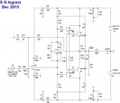
The attached circuit is what I had in mind when I posted some comments earlier on.
You can set the bias based on the size of your heatsink by adjusting VR1. For Class AB you want to set the bias so that you have enough current flowing through the output device emitter resistors to generate a voltage drop of 26mV across each resistor. If you have a large enough heatsink then you can crank it up from there, go as high as you like - although with a single pair of outputs you likely won't want more than 1.5 Amps. I bet you'll find that Class AB sounds just fine.
I don't know much about compensation of Opamps. You may need to allow for some additional components on your pcb, even if optional, so you have the flexibility to add compensation.
Class A can be easier on the power supply than Class AB, the devil is in the details.
Attachments
Thanks alot Mr Bigun!
I was bored few hours ago... were doing some metalwork in my garage and found 2 fine looking heatsinks, not that big but at least 1,5°C/W 190x35x100mm
Few steel pieces and cool case is ready... Maybe I´d like to paint the steel panels high gloss black...
I was bored few hours ago... were doing some metalwork in my garage and found 2 fine looking heatsinks, not that big but at least 1,5°C/W 190x35x100mm
Few steel pieces and cool case is ready... Maybe I´d like to paint the steel panels high gloss black...
An externally hosted image should be here but it was not working when we last tested it.
Member
Joined 2009
Paid Member
Looks good. But read up on how to compensate the opamp you plan to use and add those parts to the pcb.
Your 3-d image doesn't show the Vbe multiplier (which would imply an odd number of devices on the heatsink in total). Some folk mount it on the main heatsink between the power devices, but I prefer that it be mounted on top of one of the power output devices, instead of onto the pcb. You can thread a single mounting bolt through both the Vbe multiplier and the power device and then into the heatsink to hold them firmly together. A small thermal pad or bit of thermal grease between the Vbe multiplier and power device keeps them in good thermal contact. Then run the wires from the Vbe multiplier back to the pcb - a couple of inches is no issue but twist them together.
Built carefully it should be reliable and I think you'll like the sound, depending on your choice of opamp and other components. I'd suggest you treat the first one as a prototype, just get one channel up and running on a naked heatsink and see what you discover along the wy before committing to the final chasis.
Last edited:
- Status
- This old topic is closed. If you want to reopen this topic, contact a moderator using the "Report Post" button.
- Home
- Amplifiers
- Chip Amps
- opamp plus driver stage and output stage with its own supply, what could happen?