The 200k does not raise the noise of the inverting input by much.
It's the lower leg of the NFB that raises the noise a lot.
The -IN sees 20k||200k for an net 18k18
The noise is determined by that 18k
the 200k could be tried at 100k or 400k and there would be very little change in equivalent input noise.
Compare to a non-inverting where for the same gain one might use 20k and 2k in the NFB.
Now the -IN sees a net 1k818 for a reduction in equivalent input noise of nearly 10dB (~1/3rd)
And the previous stage has ~20k as it's load.
To match this input noise the inverting would have to adopt 2k and 20k as the NFB resistors and now the loading on the previous stage becomes 2k.
I don't think the T network in the NFB solves the noise issue of the inverting amp when gains are high.
To match this input noise the inverting would have to adopt 2k and 20k as the NFB resistors and now the loading on the previous stage becomes 2k.
I don't think the T network in the NFB solves the noise issue of the inverting amp when gains are high.
Yes, that's right. The only way around this is to use an input buffer so you can lower the Rin back down.
Last edited:
Yes, that's right. The only way around this is to use an input buffer so you can lower the Rin back down.
yes, this is exactly why i went that route ultimately. and in the end i think the result is cleaner to use BIGC (with a good buffer) rather than NIGC. getting a phase-correct result is easy enough so i don't see any downside.
Last edited:
Took me a while,
does BIGC = Buffered Inverting Gain Clone?
Are you really building a Gain Clone?
no. i have a real PSU. i was just a bit lazy typing and abused the terminology.
more properly i may have said something like:
given a good buffer i expect a better result from LM3886 operating inverted (with a buffered input) than LM3866 operating non-inverted (with or without a buffer).
I was at first very sceptical about subjective superiority of the opamp used in inverting mode. Until I tried it! For my subjective tests I used Musical Fidelity A1 line preamp section with it's two inverting stages (making complete circuit non-inverting) and simplest form of active gain control. Even with 47k series resistor at the input of the first stage I was unable to hear any problems with inverting configuration. The sound is more relaxed, musical and involving than with non inverting topology. (Beware, even the small imperfection, dirt, etc., on the pot track this kind of active gain control will cause loud noise from loudspeakers!) I used MC33079 quad opamp for complete stereo preamp.
Attachments
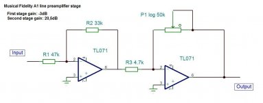
a lin pot in the inverting opamp feedback leg gives a good approximation to what the rotation and our ears expect to hear.
50k seems too high
That gives a gain of 50/4.7 * 33/47 = 7.5times (+17.5dB)
Would it be better to make R2 the adjustable section, Rin=24k and VR=50k and then use a switchable 1x or 2x in the second inverting stage 4k7 for both resistors? An extra 4k7 in parallel to R3 gives the 2x
50k seems too high
That gives a gain of 50/4.7 * 33/47 = 7.5times (+17.5dB)
Would it be better to make R2 the adjustable section, Rin=24k and VR=50k and then use a switchable 1x or 2x in the second inverting stage 4k7 for both resistors? An extra 4k7 in parallel to R3 gives the 2x
you _may_ get better results if the first stage is a unity gain non-inverting buffer. good op amps actually have quite low distortion at unity gain if they are designed to stably run that way. there is an advantage to non-inverting input buffers. their feedback loop ends close to the chip whereas the inverting topology's feedback loop includes the output network of the preceding stage. so there is a tradeoff. do you lose more from the larger loop area than you gain from the lower distortion? as usual, it depends...
buffered inverting chipamps typically get built with non-inverting buffers at the input so that the interconnect is outside any feedback loop..
if you need an inverting buffer for purposes of correct absolute phase then a possible solution is:
non-inverting buffer >> inverting buffer >> inverting power stage
OR
non-inverting buffer >> pricey mu-metal transformer >> inverting power stage
Last edited:
AndrewT,
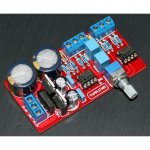
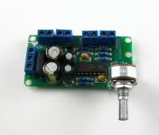
I have three versions of MF A1 line preamp stage from the schematic: a) my own rats nest perf board version: b) Chinese LJM clone kit; c) Chinese Yuan Jing clone kit.
Interesting thing is that Chinese kits deviate from the original schematic given:
1) LJM kit has 20k pot, exactly because original schematic has too much gain
2) Yuan Jing kit uses 50k lin pot (as you suggest) and 10k instead of 4k7 (again for lower overall gain)
sfthurber,
Interesting comments. It seems that the best overall compromise would be to use Baxandall active gain control that is in line with your ideas. It has non inverting first stage, inverting second stage with fixed resistor defined gain and pot that encircles both stages. There is not much circuits that so effectively solves several problems as Baxandall active gain control.
AndrewT,
Interesting comments. It seems that the best overall compromise would be to use Baxandall active gain control that is in line with your ideas. It has non inverting first stage, inverting second stage with fixed resistor defined gain and pot that encircles both stages. There is not much circuits that so effectively solves several problems as Baxandall active gain control.
that first noninverting stage does indeed give you lots of wiggle room for designing the next stage, without much downside.
- Status
- This old topic is closed. If you want to reopen this topic, contact a moderator using the "Report Post" button.
- Home
- Amplifiers
- Solid State
- opamp inverting input sounds better?