You can enlighten me some questions?
Hello!
")
C4 is there only for DC blocking in both directions. It keeps any DC present at the audio source from reaching the headphones, which preserves that fantasticly low 250uV DC output offset of the OPA1688 chip. In the other direction it keeps the OPA1688's input bias current out of the pot's wiper to prevent scratchy sounds when turning the pot (DC current will do that). Although that issue is much less of a problem here with the FET inputs on the OPA1688 than with a bipolar chip. So mainly the capacitor is there to block any source DC. I wouldn't publish a headphone amplfier circuit without a blocking capacitor in there. The chance of damaging some expensive headphones accidentally with source DC pass-through is just too great.
With C4 in place R7 then has to be there to provide a ground return path for the op-amp input bias current. If R7 isn't present the op-amp input bias current will actually charge the coupling cap up to nearly the rail voltage, which will get reflected to the output. To keep R7 from loading the pot and significantly altering its taper R7 needs to be at least 5x the value of the pot, hence the 49.9K value here.
NwAvGuy's O2 Headphone amp has a similar film blocking capacitor inbetween the gain stage and output stage for exactly the same two reasons. In the O2's case the output stage NJM4556A chips have large enough input bias currents to make that reverse blocking important, keeping the DC bias current out of the pot wiper.
A related issue is the filter that C4 and R7 forms. C4 has to be large enough to not cut off the audio at the low end. I may have actually over-done it a bit in the Super CMOY with a corner frequency all the way down at 0.9Hz or so. 2.2uF or even 1.0uF film caps should work just fine and not have an audible low end roll-off. I was just being a bit of any audio fanatic here and set the corner freuqency at 1/10 the low frequency I was trying to preserve, 10Hz, so the FR would be flat at that frequency. The good news is it apparently works great, this thing has *amazing* bass!
No cutoff or rolloff of any sort (or any boost for that matter, that is straight through from whatever the audio source is sending).You are asking a good question about stability and C4, and I believe that is one of the questions I asked johnc124 about the OPA1688 in the chip's vendor forum thread. Specifically, would the op-amp still be stable when the pot is turned all the way so that wiper end of C4 gets grounded. Notice in the schematic that effectively puts C4 between ground and the op-amp input (with R7 in parallel), something that raised some red flags in my head from past op-amp adventures. Some op-amps don't like having capacitors directly from their input to ground. But I beleive johnc124 replied it wouldn't be a problem with the opa1688. NwAvGuy's O2 headamp is the same way. Turning the volume pot all the way in one direction grounds one end of the coupling cap going to the output NJM4556A's input. If it were a problem the solution would probably be adding a small amount of series resistance, maybe another 274 ohm resistor, in series between C4 and the op amp input to isolate C4 from the input.
The noise contribution from R7 should be minimal since it is in parallel with the pot and op-amp input. Series resistors - the pot itself and the 274R RF filter resistor - will probably give you the biggest Johnson/thermal noise contribution.
On having a stable input impedance for the OPA1688, it doesn't need one thanks to the FET inputs and the tiny bias currents involved. At least in terms of unbalanced input bias current IR voltage drops across the impedances, looking out the input ports to the OPA1688, contributing to additional output DC offset. With FET inputs those impedances would have to be in the meg-ohm range to add anything noticeable to the 250uV output.
On your graph, tell us more about your circuit and what type of test you are performing. Are you using the same circuit and part values as in the Super CMOY? Appologies upfront if you are using one of my boards, I don't recognize your name as one of the boards that has gone out so far.
Last edited:
Well, just to let you all know that I'm still around. Only thing is I've been so busy I haven't had time to even peek at LTSpice. That PCB is sitting on the desk in front of me just staring at me.
I did remember something though. I took another look at the knob I pointed out previously and it's made by Kilo International, and they distribute through Digi-Key. Searching for their product line allows us to search for knobs that fit a 6 mm shaft and are 12.7 mm in diameter, which is as small as they offer. Sorry, I wanted to add a link for that, but the URL I got doesn't seem to work when copied.
Would R7 have any effect on the output offset (in combination with R8 and R12)?
I did remember something though. I took another look at the knob I pointed out previously and it's made by Kilo International, and they distribute through Digi-Key. Searching for their product line allows us to search for knobs that fit a 6 mm shaft and are 12.7 mm in diameter, which is as small as they offer. Sorry, I wanted to add a link for that, but the URL I got doesn't seem to work when copied.
To keep R7 from loading the pot and significantly altering its taper R7 needs to be at least 5x the value of the pot, hence the 49.9K value here.
Would R7 have any effect on the output offset (in combination with R8 and R12)?
That PCB is sitting on the desk in front of me just staring at me.
I have the build instructions out at the Google Drive link pretty well updated these days, when the time comes!
I have a recommended soldering sequence in there, essentially doing the less-tall stuff not near the OPA1688 first, then the chip, then everything else going from short to tall parts.Thanks for the knob info!
Would R7 have any effect on the output offset (in combination with R8 and R12)?
Luckily not because the inputs are FET with nearly zero input bias current. That is another huge plus about the OPA1688. Not only does it have inherently low input DC offset, that low input bias current won't create any significant additional with input I*R voltages.
Parallel Super CMOY THD+N tests! part 1
I finally had some time this evening to run THD+N tests on the Parallel Super CMOY with the 2 OPA1688 chips. In summary: Nice!
Compare these results with those in post #87 & #88, where I tested the single OPA1688 Super CMOY with 15/33/150 ohm loads. Especially interesting is that last two plots in post #88 back then with -1dBV input and the 15R load, where I didn't realize I was exceeding the maximum current output of the chip and measured, of course, high levels of distortion. That would have been 85mA through the 75mA maximum per channel chip. But here no such problem with -1dBV into 15R! With the two OPA1688's in parallel the maximum output current at low THD should be roughly double, 150mA per channel. In fact I doubled-down on that and ramped it up to +1dBV with the 15R load and all is still fine.
I'm only using the lithium polymer batteries here since those tests in posts #87 & #88 showed there was no significant measured difference between the lithium batteries with the 0.3 ohm internal resistance and the throw-way 9V batteries with the 5 ohms. I've also used just 15 ohm and 150 ohm loads here in the tests, no 33 ohms, to simplify things.
One of the results here is that having the second parallel OPA1688 in the "Intersil" parallel chip configuration (datasheet linked post #112 above) seems to produce no negative effects at all, at least that I can see, yet does produce the expected positive benefit of double the output current drive. If anyone spots anything in these plots that would indicate problems with that issue of delay through the first OPA1688 chip in the "Intersil" configuration, please post! I've used 1 ohm output balancing resistors in this build, so 0.5 ohm output resistance of the amp looking back into the output port.
Plots:
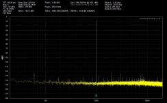
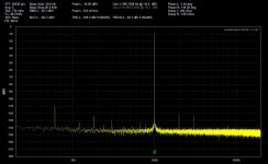
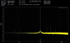
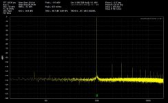
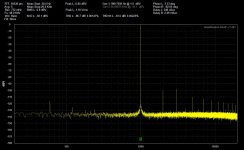
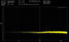
* The first 3 are all with -10dBV input at 1KHz and 48Ksps sample rate. The first is loopback of the QA401 tester showing its inherent 2nd and 3rd harmonics that have to be subtracted out of the results. Then the Parallel Super CMOY with a 150 ohm load and 15 ohm load. When those nearly -125dBV 2nd and 3rd harmonics from the tester are taken into account the results here look great.
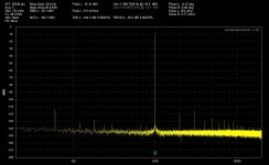
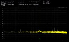
* The next 3 are the same as above but with a -1dBV input and output rather than -10dBV. loopback, 150 ohm load and 15 ohm load. Again compare the 15 ohm load result with the last two plots on post #90! Same deal, if you subtract out the now nearly -105dBV tester's harmonics from the result these look just fantastic to me, especially given that 15R load.
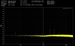
* The next 3 are the same as above but with a +1dBV input and output rather than -1dBV. loopback, 150 ohm load and 15 ohm load. Still doing great with a 15R load! Lol, try that with a OPA2134 based CMOY. More great results if the tester harmonics are taken into account. I did a "little finger" subjective chip heating test after the measurements. Both chips were warm, as expected, but not excessively so.
I finally had some time this evening to run THD+N tests on the Parallel Super CMOY with the 2 OPA1688 chips. In summary: Nice!
Compare these results with those in post #87 & #88, where I tested the single OPA1688 Super CMOY with 15/33/150 ohm loads. Especially interesting is that last two plots in post #88 back then with -1dBV input and the 15R load, where I didn't realize I was exceeding the maximum current output of the chip and measured, of course, high levels of distortion. That would have been 85mA through the 75mA maximum per channel chip. But here no such problem with -1dBV into 15R! With the two OPA1688's in parallel the maximum output current at low THD should be roughly double, 150mA per channel. In fact I doubled-down on that and ramped it up to +1dBV with the 15R load and all is still fine.
I'm only using the lithium polymer batteries here since those tests in posts #87 & #88 showed there was no significant measured difference between the lithium batteries with the 0.3 ohm internal resistance and the throw-way 9V batteries with the 5 ohms. I've also used just 15 ohm and 150 ohm loads here in the tests, no 33 ohms, to simplify things.
One of the results here is that having the second parallel OPA1688 in the "Intersil" parallel chip configuration (datasheet linked post #112 above) seems to produce no negative effects at all, at least that I can see, yet does produce the expected positive benefit of double the output current drive. If anyone spots anything in these plots that would indicate problems with that issue of delay through the first OPA1688 chip in the "Intersil" configuration, please post!
I've used 1 ohm output balancing resistors in this build, so 0.5 ohm output resistance of the amp looking back into the output port.Plots:
* The first 3 are all with -10dBV input at 1KHz and 48Ksps sample rate. The first is loopback of the QA401 tester showing its inherent 2nd and 3rd harmonics that have to be subtracted out of the results. Then the Parallel Super CMOY with a 150 ohm load and 15 ohm load. When those nearly -125dBV 2nd and 3rd harmonics from the tester are taken into account the results here look great.
* The next 3 are the same as above but with a -1dBV input and output rather than -10dBV. loopback, 150 ohm load and 15 ohm load. Again compare the 15 ohm load result with the last two plots on post #90!
Same deal, if you subtract out the now nearly -105dBV tester's harmonics from the result these look just fantastic to me, especially given that 15R load. * The next 3 are the same as above but with a +1dBV input and output rather than -1dBV. loopback, 150 ohm load and 15 ohm load. Still doing great with a 15R load! Lol, try that with a OPA2134 based CMOY. More great results if the tester harmonics are taken into account. I did a "little finger" subjective chip heating test after the measurements. Both chips were warm, as expected, but not excessively so.
Attachments
-
 -10dBV loopback 1KHz 48Ksps.jpg148 KB · Views: 411
 -
 -10dBV 150R load 1KHz 48Ksps.jpg147 KB · Views: 412
 -
 -10dBV 15R load 1KHz 48Ksps.jpg146.6 KB · Views: 401
 -
 -1dBV loopback 1KHz 48Ksps.jpg145.5 KB · Views: 394
 -
 -1dBV 150R load 1KHz 48Ksps.jpg146.2 KB · Views: 402
 -
 -1dBV 15R load 1KHz 48Ksps.jpg146.8 KB · Views: 95
 -
 1dBV 15R load 1KHz 48Ksps.jpg146.9 KB · Views: 93
 -
 1dBV 150R load 1KHz 48Ksps.jpg146.2 KB · Views: 100
 -
 1dBV loopback 1KHz 48Ksps.jpg146.6 KB · Views: 92
Last edited:
Parallel Super CMOY THD+N tests! part 2
Here is part 2 of the above Parallel Super CMOY THD+N tests. I ran out of slots for plots.
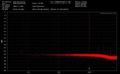
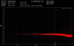
For the final 3 here I've upped the test tone to 10KHz and upped the sample rate to 24bits/192Ksps. The plots now go out to 80KHz. The input level is back to -1dBV.
The color has changed to red because I'm using the right channel on the tester here. A bunch of discussions in the equipment forum's QA401 thread and some emails with QA tech support revealed that the right channel of the tester is cleaner at 192Ksps than the right, a known thing. The two channels are essentially the same noise floor at the 48Ksps rate (used in all the tests above with the left [yellow] channel)/
The 3 plots are loopback, 150 ohm load and 15 ohm load. It has been brought to my attention that "dip" in the noise floor past 20KHz is due to noise shaping in the tester's ADC chip. The chip uses math tricks to accumulate and defer the digital rounding error at the lower frequencies and move it out to the higher frequencies past the audio band, to produce the flat noise floor through the audio band. So that dip isn't anything to do with the Parallel Super CMOY.
Here is part 2 of the above Parallel Super CMOY THD+N tests. I ran out of slots for plots.
For the final 3 here I've upped the test tone to 10KHz and upped the sample rate to 24bits/192Ksps. The plots now go out to 80KHz. The input level is back to -1dBV.
The color has changed to red because I'm using the right channel on the tester here. A bunch of discussions in the equipment forum's QA401 thread and some emails with QA tech support revealed that the right channel of the tester is cleaner at 192Ksps than the right, a known thing. The two channels are essentially the same noise floor at the 48Ksps rate (used in all the tests above with the left [yellow] channel)/
The 3 plots are loopback, 150 ohm load and 15 ohm load. It has been brought to my attention that "dip" in the noise floor past 20KHz is due to noise shaping in the tester's ADC chip. The chip uses math tricks to accumulate and defer the digital rounding error at the lower frequencies and move it out to the higher frequencies past the audio band, to produce the flat noise floor through the audio band. So that dip isn't anything to do with the Parallel Super CMOY.
Attachments

Last edited:
I may be wrong but in a quick ltspice sim with a few hundred ohms + 1 nF it seems borderline stable. I'd give it some gain and redo the compensation.
If you have it set up for 1x gain with the 1nF caps make sure you have C7 & C8 omitted. johnc124 pointed out in a post those will pretty much negate the usefulness of C13 and C14. And conversely if it is set up for gains greater than 1x then C13 and C14 are left off, C7 & C8 populated, and one of the C13/C14 pads jumpered to a ground hole on the board next to them which grounds one end of R8 and R9.
I've attached a PDF of the schematic below and I've added all of these instructions up at the top.
I agree, it will be quite interesting to see what the testing shows! Hopefully next week if I get some time. I want to test it with 16R and 150R, both with 470pF, 1nF, and 2.2nF. Lets see if something breaks.
The one I am building is unity gain, I am waiting on 3 capacitors to power up and test.
Alex
Good progress! With any luck I'm going to try updating the BOM and build instructions to include the parallel version of the Super CMOY this weekend. It is just the extra OPA1688 chip, four 1R 1/8W balancing resistors, and the two extra 0.1uF decoupling caps on the 2nd chip that are different. I think I'm going to add them to the existing BOM and highlight those in orange. The build instructions are the same except for adding those same parts and end-mounting some of the resistors.
I'll also create sub-folders at the Google Drive link in the schematic and layout folders for the parallel super CMOY. Lol I hadn't added anything yet because I was worried that the THD tests would show something horrific due to that Intersil paralleling method, but they came out great! Maybe the unpleasant surprise will come instead with phase margin / stability testing with the capactive loads, like xnor says. Will be interesting!
Attachments
Last edited:
lol, I'm old enough that I first learned programming on a FORTRAN system that used an actual deck of paper punch cards.
A good programmer can write FORTRAN in any language.
I usually see that written as "a bad programmer can write Fortran in any language", referring to spaghetti code. Back in the class-less GOTO days.
But yes, defnitely, if someone sticks to just syntax available in the target language in the other language, it should (largely) work, given that the target language should always be a consistent set of commands.
Lol, after Fortan I learned BASIC on a freestanding Teletype terminal hooked in over a phone line to a local University mainframe. That thing probably ran at 100 baud or so, tops. The entire machine would shake when it typed. The letter "O" and periods would punch holes right through the paper. Yet that was just the slickest thing at the time, real-time program execution without having to send in punch cards and wait several days.
Back in the class-less GOTO days. But yes, defnitely, if someone sticks to just syntax available in the target language in the other language, it should (largely) work, given that the target language should always be a consistent set of commands.
Lol, after Fortan I learned BASIC on a freestanding Teletype terminal hooked in over a phone line to a local University mainframe. That thing probably ran at 100 baud or so, tops. The entire machine would shake when it typed. The letter "O" and periods would punch holes right through the paper.
Yet that was just the slickest thing at the time, real-time program execution without having to send in punch cards and wait several days. That would have been one of these guys.
Teleprinter
Reading about this old stuff is always fascinating for us young whippersnappers. I mean, by the time I had anything to do with computers, 14400 bps modems were all the rage...
Teleprinter
Reading about this old stuff is always fascinating for us young whippersnappers.
I mean, by the time I had anything to do with computers, 14400 bps modems were all the rage...Well I am 99.9% complete and just need one more 1uf decoupling cap. I was communincating with AGDR and he thought it would be fine to turn in on and see if it worked.
Well I did and again "Its Alive!" and sounds really good.
I will do some in depth compairisions with the single 1688 version as well as the O2, ODA , and non inverting O2.
What I can say right now after two hours od solid listening with just it and two sets of headphones that its a real winner.
The amp is wired with a 1x or unity gain, and I wanted to see if there would be enough umph to power my Beyer T90's 250 ohms. I am using the good ole throw away akalines Duracells to be exact.
I have been using these cells for several weeks and they show 7.44 vdc under load. connected and playing music. The amp drive the 250 ohm Beyers to painful levels, no issue with having to mess with a higher gain setting.
I also have the better 5% Wima coupling caps installed vs the 10%...but I dont really know if that matters or not.
The amp is dead silent with the volume cranked up all the way, no hiss, hum or any audible noise, just quiet silent background, makes listening a real pleasure. Especially when playing at lower volumes.
The bass on this thing is something else, its the only thing right now I am wondering about in a good way but its a subjective thing, I will do some blind AB testing in the next few days.
An amp to me should be a straight wire with gain. Just simple and do your thing...and this amp definitely does that well so far.
The muting relay works as designed and its silent, no popping or thumps with turn on or off. Also the neat VERY small TPS 3701 works well, unhook one battery and it shuts off cleanly, put the battery back in and it powers up cleanly. That chip is the only really challenging chip other than its smaller cap on the same small board! I use a normal 50 watt sized soldering iron!! and its a challenge but so far I am two for two!! Solder wick is magic!!Ha!
Ok for now, stay tuned for how it sounds or rather how it doesnt sound!
Alex
Last edited:
Well I did and again "Its Alive!" and sounds really good.
Thank you for the listening comments! I've been pretty impressed with the silent background too.
There was more of a chance for noise with this one due to the FET-input chips, now on two chips in a row, but it seems to be well below audible. Also having two fet chips in a row the voltage noise should be uncorrelated, so the noise would likely add as rms (lower total number).The low-value feedback resistors should be helping with thermal noise reduction.
Yeah the super flat low end frequency response on this one with those 3.3uF caps (0.95Hz corner) just lets any bass from the source plow right on through!
I have my Akerberg-Mossberg notch filter just sitting here that I haven't had time to mess with in a couple of months. I really want to re-run those THD+N scans with a notch filter to edit out the QA401 tester's harmonics.
Last edited:
C-load testing: single and double stable with 2.2nF load! Part 1
I did the capacitive load testing on both the single and double (parallel) OPA1688 Super CMOYs today and what a surprise - in a good way - BOTH are completely stable with a 2.2nF (= 0.0022uF) load with both 16 ohm and 150 ohm resistances! Both of the Super CMOYs tested were built up with 2x voltage gain.
But gets even better. As a double check on the test procedure I unhooked the resistive load entirely on both amps, leaving the CMOY to power the purely reactive capacitive load. They *should* oscillate, of course, at some level of purely capacitive load as the phase margin shrinks. The test capacitors are all C0G MLCC ceramic, very little ESR. Sure enough, both oscillated with a 2.2uF purely capacitive load, as expected, although the parallel not nearly as much as the single chip (details and plots below).
But guess what? The parallel Super CMOY is completely stable with a 1nF purely capacitive load! That is just fricking amazing. Good work TI and johnc124 for the compensation capacitor tips in the datasheet. I'm equally amazed that both the single and double chip Super CMOYs are stable at 2.2uF with the resistive loads.
DETAILS
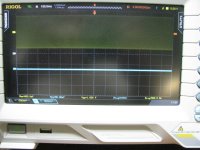
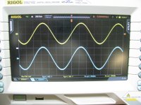
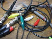
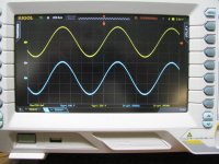
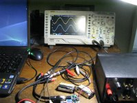
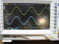
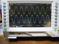
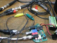
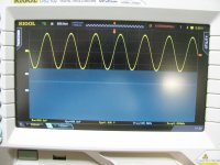
* The first photo below is the test setup. That is a Victor low-THD 1KHz oscillator feeding the (double chip parallel) Super CMOY (yellow trace on the scope). The output of the Super CMOY is the blue trace, with the two test clips holding the load resistor. When I start adding the capacitor I have a second set of test clips. The clips themselves will add a bit of capacitance to the load, of course. An argument could be made that the inductance of the test leads might partially isolate the test capacitance at the end, but that would also be true then of real headphone cables, which is what this whole effort is modelling.
* The next plot is with a 1.5Vp-p (about 1Vrms) input signal and 16 ohm purely resistive load. No load capacitor yet.
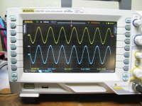
* Next is the same as above but with a parallel 470pF output load added. No visible change or oscillation. I was expecting just this much capacitance to be stable.
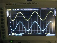
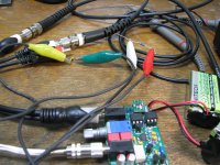
* Next photo and plot are now with 16R + 1nF in the test clips. The photo is just to show the test setup. That is an axial 1nF C0G MLCC cap. Again zero oscillation. I didn't show it here but I ran the scope time base up and increased the sensitivity looking for higher frequency oscillation. Just nothing.
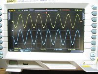
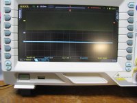
* Next photo is same as the above, but now with the 2.2nf cap. So 16R + 2.2nF. No oscillation! The third scope shot is with the time base run up looking for higher frequency stuff. I didn't take a photo but I ran the sensitivity up to 10mV at one point. No oscillations.
I did the capacitive load testing on both the single and double (parallel) OPA1688 Super CMOYs today and what a surprise - in a good way - BOTH are completely stable with a 2.2nF (= 0.0022uF) load with both 16 ohm and 150 ohm resistances! Both of the Super CMOYs tested were built up with 2x voltage gain.
But gets even better.
As a double check on the test procedure I unhooked the resistive load entirely on both amps, leaving the CMOY to power the purely reactive capacitive load. They *should* oscillate, of course, at some level of purely capacitive load as the phase margin shrinks. The test capacitors are all C0G MLCC ceramic, very little ESR. Sure enough, both oscillated with a 2.2uF purely capacitive load, as expected, although the parallel not nearly as much as the single chip (details and plots below). But guess what? The parallel Super CMOY is completely stable with a 1nF purely capacitive load!
That is just fricking amazing. Good work TI and johnc124 for the compensation capacitor tips in the datasheet. I'm equally amazed that both the single and double chip Super CMOYs are stable at 2.2uF with the resistive loads. DETAILS
* The first photo below is the test setup. That is a Victor low-THD 1KHz oscillator feeding the (double chip parallel) Super CMOY (yellow trace on the scope). The output of the Super CMOY is the blue trace, with the two test clips holding the load resistor. When I start adding the capacitor I have a second set of test clips. The clips themselves will add a bit of capacitance to the load, of course. An argument could be made that the inductance of the test leads might partially isolate the test capacitance at the end, but that would also be true then of real headphone cables, which is what this whole effort is modelling.
* The next plot is with a 1.5Vp-p (about 1Vrms) input signal and 16 ohm purely resistive load. No load capacitor yet.
* Next is the same as above but with a parallel 470pF output load added. No visible change or oscillation. I was expecting just this much capacitance to be stable.
* Next photo and plot are now with 16R + 1nF in the test clips. The photo is just to show the test setup. That is an axial 1nF C0G MLCC cap. Again zero oscillation. I didn't show it here but I ran the scope time base up and increased the sensitivity looking for higher frequency oscillation. Just nothing.
* Next photo is same as the above, but now with the 2.2nf cap. So 16R + 2.2nF. No oscillation! The third scope shot is with the time base run up looking for higher frequency stuff. I didn't take a photo but I ran the sensitivity up to 10mV at one point. No oscillations.
Attachments
Last edited:
C-load testing: single and double stable with 2.2nF load! Part 2
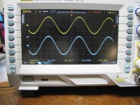
Next up are the same tests as above in part 1, but now with a 150 ohm resistor instead of 16 ohm. These test are still with the Parallel dual-chip Super CMOY
* 150 ohm purely resistive, with no load capacitor yet.
* 150 ohm + 470pF
* 150 ohm + 1nF
* 150 ohm + 2.2nF
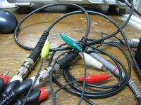
The next set of tests are with a single chip Super CMOY. I skipped right to the 2.2nf load case here since it the the most likely to oscillate.
* The next 3 show the test setup and results for 2.2uF C0G MLCC. Just the 150R load is shown here, but I tried it with both the 16R and 150R. No oscillations! The 3rd photo just shows the time base on the scope run up with the input signal still applied. The 4th is with the input signal to the amp removed.
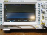
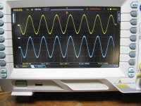
The final two here are now with the purely capacitve load, resistor removed, which is *expected* to oscillate - and does! The whole point of these tests is a double-check on my test methods here. If the amp didn't oscillate at some fairly heavy level of output purely-capacitive load like this, something would be wrong.
* Here the 2.2nF capacitor is still across the Super CMOY output (single chip amp still) but notice the load resistor is unclipped from a test lead. Purely reactive load, and the results don't dissapoint. Oscillation, as expected.
Next up are the same tests as above in part 1, but now with a 150 ohm resistor instead of 16 ohm. These test are still with the Parallel dual-chip Super CMOY
* 150 ohm purely resistive, with no load capacitor yet.
* 150 ohm + 470pF
* 150 ohm + 1nF
* 150 ohm + 2.2nF
The next set of tests are with a single chip Super CMOY. I skipped right to the 2.2nf load case here since it the the most likely to oscillate.
* The next 3 show the test setup and results for 2.2uF C0G MLCC. Just the 150R load is shown here, but I tried it with both the 16R and 150R. No oscillations! The 3rd photo just shows the time base on the scope run up with the input signal still applied. The 4th is with the input signal to the amp removed.
The final two here are now with the purely capacitve load, resistor removed, which is *expected* to oscillate - and does! The whole point of these tests is a double-check on my test methods here. If the amp didn't oscillate at some fairly heavy level of output purely-capacitive load like this, something would be wrong.
* Here the 2.2nF capacitor is still across the Super CMOY output (single chip amp still) but notice the load resistor is unclipped from a test lead. Purely reactive load, and the results don't dissapoint. Oscillation, as expected.
Attachments
-
 IMG_4382.JPG241.2 KB · Views: 67
 -
 IMG_4381.JPG240.5 KB · Views: 57
 -
 IMG_4380.JPG344.6 KB · Views: 61
 -
 IMG_4374.JPG245.1 KB · Views: 52
 -
 IMG_4373.JPG266.5 KB · Views: 57
 -
 IMG_4372.JPG263 KB · Views: 63
 -
 IMG_4371.JPG231.3 KB · Views: 65
 -
 IMG_4383.JPG236.4 KB · Views: 55
 -
 IMG_4384.JPG379.5 KB · Views: 72
 -
 IMG_4385.JPG204.7 KB · Views: 73
Last edited:
- Home
- Amplifiers
- Headphone Systems
- OPA1688 Super CMOY, 2x 9V with real ground and headphone relay - PCBs