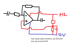
Would you be able to draw what you mean?
I understand the need to bias it to half the op amp supply voltage, however i wouldnt be able to place the components on the diagram myself.
The op amp i am using is the LME49720 which can only support 16vdc, which was the inital reason for using the 7812 to power it.
http://uk.rs-online.com/web/p/operational-amplifiers/7616217/
Last edited:
I understand the need to bias it to half the op amp supply voltage,
The op amp i am using is the LME49720 which can only support 16vdc, which was the inital reason for using the 7812 to power it.
This op amp takes up to +/-17V. Like most, it normally is used with two equal bipolar supplies,
but it can be used with a single supply up of to +34V if the inputs are properly biased at half the supply.
Thats fantastic, in that case i will run it on the 24-28v using the potential divider as you mentioned.
I would assume a potenital divider would be more suitable than a zener in this situation as the voltage of the batteries will change from 28v at full charge to 24v almost depleted. With a potential divider, the refernce voltage will change with the supply voltage, instead of the fixed reference voltage generated by the zener?
I notice that you have left out the 100k resistor from the previous drawings which connected from the -ve of the output cap to 0v. Was this unnecessary when not using a zener diode?
The cap should always be included unless you know for certain that whatever it will connect to has a similar resistor at its input. The resistor ties the cap to ground and defines the output at 0.000 volts DC. If the input stage of the power amp also has a cap (and no resistor) then with two caps in series, one could end up with a reverse DC bias due to normal cap leakage currents. The resistor eliminates that possibility.
The resistive divider is fine for most conditions. The downside is that there will be some slight "modulation" of the battery voltage as you turn up the volume and that will reflect in the voltage the divider produces. The cap virtually eliminates that but is less effective at low frequency. In other words imagine the battery voltage varying 24 to 28 to 24 to 28 slowly. The reference voltage will follow that... the zener reference won't. The fact the zener clamps at 12 volts even thogh the battery might be 24 or 28 etc only means a slight asymmetry when clipping is reached (max output). A non problem.
The resistive divider is fine for most conditions. The downside is that there will be some slight "modulation" of the battery voltage as you turn up the volume and that will reflect in the voltage the divider produces. The cap virtually eliminates that but is less effective at low frequency. In other words imagine the battery voltage varying 24 to 28 to 24 to 28 slowly. The reference voltage will follow that... the zener reference won't. The fact the zener clamps at 12 volts even thogh the battery might be 24 or 28 etc only means a slight asymmetry when clipping is reached (max output). A non problem.
That being said, would you recommend the Zener solution instead of the resistor potential divider?
Battery life is the most important thing to this project, as its a backpack that plays radio linked music (via a 864mhz IEM link) on the mass street skates in London. Once the volume is set during a skate, its unlikely to be adjusted for at least an hour so a slight distortion when changing the volume would be acceptable.
Or am i completely over-thinking something that is going to have a negligible effect anyway?
Last edited:

Ahh you beat me to it.
Many thanks!
After sleeping on it i realized the ground symbol on the datasheet meant to goto the reference voltage and not -ve. But you beat me to it before i could hide my error!")
Just for my own knowledge, why is it that we are inputting to the op amp via the - instead of the +? As the data sheet high pass filter example shows it going into the +.
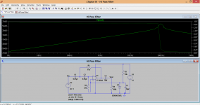
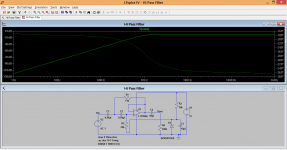
Also thanks for showing the output from LTSpice, i have just installed it and will have a good play around.
Many thanks!
After sleeping on it i realized the ground symbol on the datasheet meant to goto the reference voltage and not -ve. But you beat me to it before i could hide my error!
Just for my own knowledge, why is it that we are inputting to the op amp via the - instead of the +? As the data sheet high pass filter example shows it going into the +.
Also thanks for showing the output from LTSpice, i have just installed it and will have a good play around.
- Status
- This old topic is closed. If you want to reopen this topic, contact a moderator using the "Report Post" button.
- Home
- Source & Line
- Analog Line Level
- Op amp band pass filter connection problems