**picture edited to show correct voltages**
Hey All,
I have built a backpack speaker system that uses an Sure STA 508 4 channel class D amp and it works great.
However i am trying to get the most out of a mid bass speaker by using a band pass filter made of an op amp.
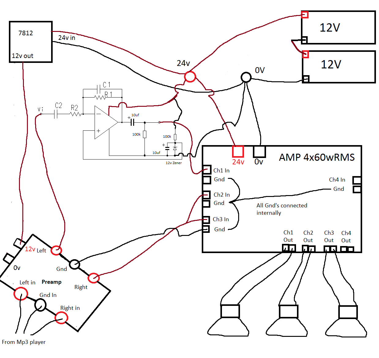
I am having problems getting my head around the connections to ground, as the amp runs on 24v and the preamp and op amp runs on 12v.
I have a split rail power supply made from LM317s and a LM337 which take the 24v and turn it into -6, Gnd and +6v which powers both the op amp and the preamp.
The op amp on its own works fine when i test it with a line source and headphones using the split rail power supply.
The problem arises when i connect it into the amp.
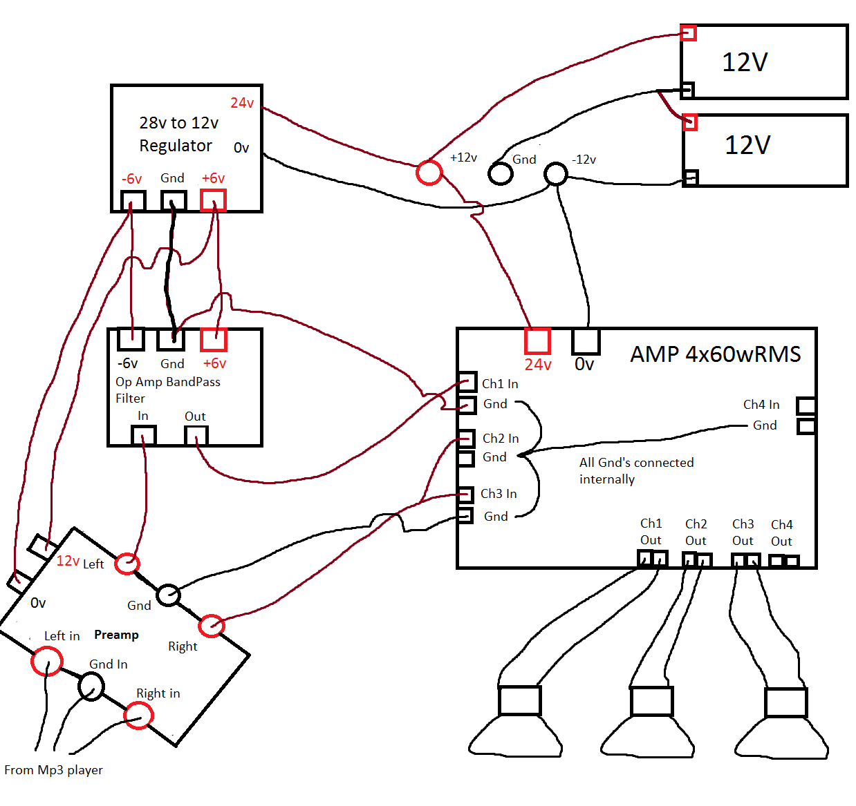
Can someone comment on the ground connections in the picture?
Please excuse the awfull paint picture!
Hey All,
I have built a backpack speaker system that uses an Sure STA 508 4 channel class D amp and it works great.
However i am trying to get the most out of a mid bass speaker by using a band pass filter made of an op amp.
I am having problems getting my head around the connections to ground, as the amp runs on 24v and the preamp and op amp runs on 12v.
I have a split rail power supply made from LM317s and a LM337 which take the 24v and turn it into -6, Gnd and +6v which powers both the op amp and the preamp.
The op amp on its own works fine when i test it with a line source and headphones using the split rail power supply.
The problem arises when i connect it into the amp.
Can someone comment on the ground connections in the picture?
Please excuse the awfull paint picture!
Last edited:
Just clarify something...
The main power amp you have drawn as connecting across 24 volts (two series connected batteries) but the power amp shows a plus and minus 24 volts. Conventionally that would imply a plus 24 volt, then a ground, then a minus 24 volt rail.
As you say it works I'm assuming it actually runs on a single 24 volt rail.
Its important we know this. Does the point you have marked -24 volts on the power amp actually connect internally to the point marked ground on the power amp ?
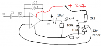
This is the schematic of the bandpass filter.
It appears that you are trying to have two different grounds, at different potentials.
One terminal of the amp, probably the -24V terminal, is connected internally to ground.
Check with an Ohm meter.
Your split power supply cannot work this way, since its ground is 12V above the amp's ground.
The easiest way to make this work is to run the amp only on the upper 12V battery, with the common battery connection grounded.
THen the lower battery is used for the negative supply.
Last edited:
OK ")
I was trying to get an idea of how it was all configured with the above questions because as drawn its not really correct... so we really do need to know so that we can be sure nothing goes pop
Also... assuming normal linear regulators (7812, 7912 etc) then you can not get -/+ 12 volts from just two 12 volt batteries. The regulators would need be to a special isolated type to work as are wanting to show.
There are to many inconsistencies as it stands to advise you. Do you see
The power amp as drawn needs a split -/+24 volt supply, 48 volts in total. That is what you have drawn. But without the ground. We need to build on that and work out what you have.
Excellent !
What this is going to come down to is this. You will either need to convert the opamp filter to run on a single 24 volt rail (not a split rail) or if that isn't possible you would need a simple to use DC/DC convertor giving an isolated dual rail.
As drawn its dead easy to rig the opamp for single rail. You would then get rid of the regulators (not needed) and AC couple the opamp output to the main amp input.
The problem you have is wanting two grounds that are going to be at different voltages... not possible as you have it drawn.
All we do is this.
1/ Couple the power amp up as shown running on 24 volts.
2/ The front end preamp you have marked as running on 12 volts will either need a single 7812 type regulator feeding it (the reg input coming from the plus 24 volts) or you could power it from the junction of the batteries (so it runs off the lower one).
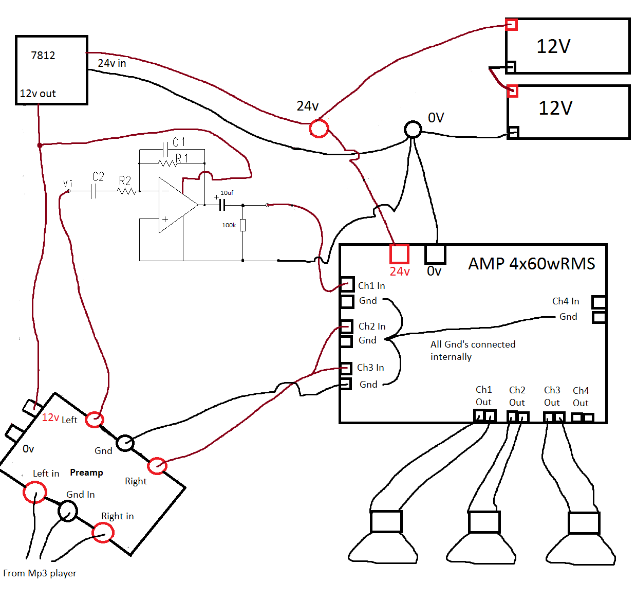
3/ That leaves your opamp. You need to add a capacitor (say 10uf) to the output together with a resistor (say 100k) from the output side of the cap to ground.
4/ To convert the opamp to single rail all you do is connect the non inverting input to 12 volts. That is best derived from a zener diode.
I'll draw the essentials for you.
What this is going to come down to is this. You will either need to convert the opamp filter to run on a single 24 volt rail (not a split rail) or if that isn't possible you would need a simple to use DC/DC convertor giving an isolated dual rail.
As drawn its dead easy to rig the opamp for single rail. You would then get rid of the regulators (not needed) and AC couple the opamp output to the main amp input.
The problem you have is wanting two grounds that are going to be at different voltages... not possible as you have it drawn.
All we do is this.
1/ Couple the power amp up as shown running on 24 volts.
2/ The front end preamp you have marked as running on 12 volts will either need a single 7812 type regulator feeding it (the reg input coming from the plus 24 volts) or you could power it from the junction of the batteries (so it runs off the lower one).
3/ That leaves your opamp. You need to add a capacitor (say 10uf) to the output together with a resistor (say 100k) from the output side of the cap to ground.
4/ To convert the opamp to single rail all you do is connect the non inverting input to 12 volts. That is best derived from a zener diode.
I'll draw the essentials for you.
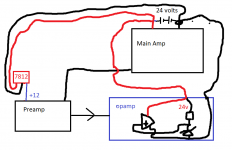
Looking at your picture, in the top one there is a lead running from 0v to the op amps, but in the second picture there isnt a 0v lead. Could you tell me if a connection to 0v is needed for the op amp? I am assuming it will need a 0v connection.
Also your top pic there is not a 0v for the 7812, i assume i will need one there.
Below is an updated picture of what i think i should do, however there should be a 0v lead running to the op amp somehow?
Also your top pic there is not a 0v for the 7812, i assume i will need one there.
Below is an updated picture of what i think i should do, however there should be a 0v lead running to the op amp somehow?
Top picture and the 7812... the black lead from centre pin to the lower battery negative is 0 volts (ground... 0v and ground are now the same point in a single rail).
You will have to observe good practice with the grounds as with any design. As drawn there is ground continuity via the signal ground from the preamp back through the power amp and back to the battery. Imagine the 7812 is wired at the battery. 24V in, centre lead to 0v. You then take the 12 volt output to the preamp.
The ground for the opamp (pin 4, 100k,zener, cap etc) goes back to the battery negative (ground).
Electroylitics are ideal. You want a 25v or higher and the plus end will go to the opamp output.
That looks OK. In practice the 7812 should have a small cap (10uf electro is ideal) soldered between the centre pin (the reg ground) and its output. You can solder the cap direct to the pins which is best as it gets it closest. That's standard practice for any reg to ensure stability. You can add the same at the input pin to, another cap to the reg centre ground pin.
Other easy options...
If wanted to eliminate the zener, its cap and the feed resistor then you can obtain plus 12 volts from the 7812 to bias the opamp.
And a low component count option...
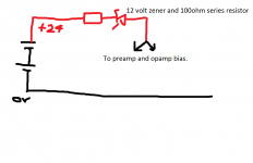
If the current draw of the preamp and opamp circuits is low (say under 80 milliamps) then you could go ultra simple and obtain "around" 12 volts for the preamp by simply adding a series zener diode to the supply to these. The zener would drop 12 volts and so with 24 volts applied you get 12 volts for the preamp. As the batteries fall the 12 volt drop across the zener is constant and so the preamp sees a slightly lower voltage... probably of no consequence as you will never go below around 11 volts per battery. The opamp bias is derived from this as well... no parts needed.
Other easy options...
If wanted to eliminate the zener, its cap and the feed resistor then you can obtain plus 12 volts from the 7812 to bias the opamp.
And a low component count option...
If the current draw of the preamp and opamp circuits is low (say under 80 milliamps) then you could go ultra simple and obtain "around" 12 volts for the preamp by simply adding a series zener diode to the supply to these. The zener would drop 12 volts and so with 24 volts applied you get 12 volts for the preamp. As the batteries fall the 12 volt drop across the zener is constant and so the preamp sees a slightly lower voltage... probably of no consequence as you will never go below around 11 volts per battery. The opamp bias is derived from this as well... no parts needed.
Attachments
It would certainly work provided you now used something like 6.2v zener to set the midpoint reference for the opamp but 12 volts is seriously limiting the peak voltage swing the opamp can deliver. Typically you would see only around -/+4.5 volts or so as available signal swing before clipping. That's still plenty, as long as you are aware of the whys and wherefores. If the volume control is before the opamp stage then you should be OK. After and there is a definite risk of clipping on high level transients.
Edit... I see you have the opamp + input now connected to 0v. That won't work. It must be biased to half the opamp supply voltage. As you are using a regulated 12 volts supply you can could use a simple resistive divider (two 10k's with a 10uf cap across the lower one).
Edit... I see you have the opamp + input now connected to 0v. That won't work. It must be biased to half the opamp supply voltage. As you are using a regulated 12 volts supply you can could use a simple resistive divider (two 10k's with a 10uf cap across the lower one).
- Status
- This old topic is closed. If you want to reopen this topic, contact a moderator using the "Report Post" button.
- Home
- Source & Line
- Analog Line Level
- Op amp band pass filter connection problems