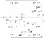
The Siemens amplifier seems to be a decent design (inhttp://www.diyaudio.com/forums/solid-state/162644-siliconix-siemens-nmos-amplifiers.html). But it must be better to use a simple bias control. A while ago I was considering the Class A amplifier in the attachment. It has the same bias control as in an old Pass design.
Attachments
can you post this schema or send direct to me - my address:I have the schematics of the Cabasses AM/AS1000 amplifiers which show class G output stage topology where the inner devices are N-channel MOS-FETs IRFP240, whereas the outer devices are complementary MOS-FETs IRFP9150/IRFP150, driven by a differential amplifier.
kirschner-hifi@tiefbasswiedergabe.de
can you post this schema or send direct to me - my address:
kirschner-hifi@tiefbasswiedergabe.de
Cabasse have kindly acknowledged the publication of the schematics.
Your can find it here : Manuel de maintenance Cabasse AM1000/AS1000 - Forum Cabasse
Thank you very much for this URLCabasse have kindly acknowledged the publication of the schematics.
Your can find it here : Manuel de maintenance Cabasse AM1000/AS1000 - Forum Cabasse
From the same author: The Circlophone:another approach in this context
http://www.diyaudio.com/forums/solid-state/154388-its-cheap-its-n-its-dirty-its-circlomos.html
http://www.diyaudio.com/forums/solid-state/189599-my-little-cheap-circlophone.html
http://www.diyaudio.com/forums/soli...tion-parts-accessories-beginner-friendly.html
http://www.diyaudio.com/forums/power-supplies/212945-boostor-ideal-companion-circlophone-move.html
From the category "driving by phase splitting driver transformers" (go to number 3) from post #1
this project rises up:
http://www.diyaudio.com/forums/pass-labs/216616-f6-amplifier.html
this project rises up:
http://www.diyaudio.com/forums/pass-labs/216616-f6-amplifier.html
I note by this circuit topologies, that I cannot say bei number 3), 4), 8) and 9) clearly the possibility of class A/B operation
1) driving through differential driver stages - class A/B is possible
2) driving through phase splitting transistor (Totem-Pole like Bengt Ollson, Futterman or MOSFET-DOZ) - class A/B is possible
3) driving through phase splitting driver transformers - only pure Class A ?
4) driving through current mirror phase shifter - only pure Class A ?
5) Quasi complementary output stages - class A/B is possible
6) Version orf German's company "Protovision" - class A/B is possible
7) Version of NAD integrated amp "306" - class A/B is possible
8) driving through two op amps - only pure Class A ?
9) Circlotron (lowest distortion) - only pure Class A ?
3), 4), 8, 9) - all of these can work in class AB.
1), 2), 3), 4), 8) are all really based on different phase splitters rather than any other fundamental difference.
Any totem-pole output can in theory (but not always practical) be 'inverted' like some QSC or Hafler designs where what is normally the output is grounded and the power supply center is the output (i.e. floating power supply). Fundamentally bridged designs like the circlotron cannot really be inverted (circlotron can be seen as two bridged single-ended amplifiers). Keep in mind that every push-pull amplifier can be seen as a combination of two single ended amplifiers and this has nothing to do with SE only being able to work in class A. You could just as well under or overbias a SE design but it would normally just get you asymetric clipping (in the extreme, you can only get a small part of one half-period). The reason push-pull can work class AB even though it's notionally made of two SE amps, is that one half can be biassed so that it reproduces the part of the waveform that would be missing if you only looked at one SE half.
Most PP totem-pole designs that do not use the standard quasicomp arrangement (darlington of one polarity, CFP of the other - exploiting the fact that the 'front' of a darlington and CFP are complementary, but the second stage is of the same polarity) have voltage gain on the output devices in order to get good symmetry. Mostly it's done by bootstrapping the drive of one of the devices to it's source, so that there is equal and complementary driving signal between G-S of both devices. Although one of the devices has it's 'output' on the source, this is NOT a source follower, rather an inverted SE 'half' where the power supply and the load have exchanged places.
Unlike BJTs, MOSFET there is a difference in symmetry of operation for such output stages as described above. With BJTs the base current of one of the output transistors flows out the emitter and through the load, whereas for the other it goes to the power supply. Unlike BJTs, this slight imbalance is as constant as beta is of the output device. It behaves consistently to the output device itself and does not intrudice higher orders of nonlinearity in itself. With MOSFETs the same happens but the current closing through the load in one of the devices in the input capacitance charge-discharge current of the MOSFET. Although BJTs also have non-linear input capacitances and there is a similar mechanism, the beta mechanism is absent in MOSFETs and further, the capacitancec are larger and exhibit a different kind and magnitude of nonlinearity, which is the principal source of asymmetry in such stages, assuming the MOSFETs in both PP halves are matched well enough. This may well introduce more higher order asymetry behavior than in the BJT versions of the same topology.
The circlotron is the simplest inherently differential and symmetrical output stage and does not suffer from the above mechanisms, given matched devices in it's halves, it remains completely symmetrical. If it's driven WRT centerpoint of it's load, it also has unity coupling, drain voltage is fed back inverted in full to the sources (with pentode-like output curves like the MOSFET has, this normally means a gain approaching 2 WRT input drive), so there is very strong feedback even though output devices have voltage gain. This also gives it a characteristic closest to a follower, including relatively low output impedance and distortion. However, you pay for all that by having independent floating power supplies, and the output of a circlotron also drives any capacitances between them.
Last edited:
Which good available amplifiers and amplifier kits with circlotron output stage are on the marked (except Thorens TEM3200) ??
Hi Tiefbass !
Check this: http://www.diyaudio.com/forums/solid-state/270239-i-call-infinitron.html
Best Regards !
The Kaneda by number 1 from post #1 - go to
http://peufeu.free.fr/audio/schemas/Kaneda_Mosfet.jpg
had obviously a predecessor - go to message #199 under
Kits Kaneda
and post #244 under
http://www.diyaudio.com/forums/soli...omplementary-power-output-25.html#post4687437
http://peufeu.free.fr/audio/schemas/Kaneda_Mosfet.jpg
had obviously a predecessor - go to message #199 under
Kits Kaneda
and post #244 under
http://www.diyaudio.com/forums/soli...omplementary-power-output-25.html#post4687437
Last edited:
")
hi tief,
maybe you can add this to the list :
ECLER PAM4100/6100 ECLER PAM4100 PAM6100 SM Service Manual download, schematics, eeprom, repair info for electronics experts
ARCAM alpha 10 ARCAM ALPHA 10 10P Service Manual download, schematics, eeprom, repair info for electronics experts
NAD 208 NAD 208 POWER AMPLIFIER Service Manual download, schematics, eeprom, repair info for electronics experts
- Status
- This old topic is closed. If you want to reopen this topic, contact a moderator using the "Report Post" button.
- Home
- Amplifiers
- Solid State
- Only N-Channel MOSFETs (NMOS); better Audio from non complements by Audio Power?