Worth looking at -- http://www.diyaudio.com/forums/pass-labs/121228-f5-power-amplifier-239.html#post2923127
Post#11910
Post#11910
So it looks like I have some work.
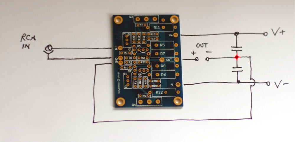
1. Connect the RCA grounds together
2. Remove the Ground wire from one of the RCA jacks to the board
3. Add a wire from the amp board ground that was disconnected from the rca jack above to the other amp board
4. Connect the two ground points as in the photo from the post above.
So the ground path goes from RCA left to RCA right to amp board right to amp board left to star ground on the PSU PCB. Clear as mud? I'll try it tonight and see what happens.
My bias tends to drop fairly dramatically when I take the cover off. Maybe 30 mV or so. As such, trying to set it with the top off and then watching the bias increase with the top mostly on has been a bit iterative. I'm thinking that perhaps I need to drill some vent holes or slots since the small gap I have built in doesn't seem to be doing much to keep things as cool as possible.
That said, I still have no problem holding my hands on the sinks indefinitely. Sure, it's hot, but not to the point where I need to remove my hands. The aluminum pieces that make up the bottom probably help a little bit in that regard as well. Net conclusion though, is that these sinks are fine!
That said, I still have no problem holding my hands on the sinks indefinitely. Sure, it's hot, but not to the point where I need to remove my hands. The aluminum pieces that make up the bottom probably help a little bit in that regard as well. Net conclusion though, is that these sinks are fine!
oneplustwo said:My bias tends to drop fairly dramatically when I take the cover off.
Yep, the thermistors get some airflow and immediately cool down, changing the bias.
Drill a couple of holes in the top so there is some natural airflow inside the case and that issue will go away.
")
Sorry to be a total pain but as I gather that the thermistors are being affected by the temperature inside the case why not just try to stick them to the drain leg of the mosfets?
I understand that maybe using glue and having to take it of is a pain so even just to try you could use a piece of string or little heath shrink tube.
My thinking is that as the temperature is much higher there (The drain leg and the metal back of the mosfets is practically a single piece of metal) they may be less sensitive to the case temperature.
Don’t get me wrong is not my intention to dictate how you should build your F5 is just that maybe 5 minutes top of work may save you quite a bit of time in the long run.
Sorry to be a total pain but as I gather that the thermistors are being affected by the temperature inside the case why not just try to stick them to the drain leg of the mosfets?
I understand that maybe using glue and having to take it of is a pain so even just to try you could use a piece of string or little heath shrink tube.
My thinking is that as the temperature is much higher there (The drain leg and the metal back of the mosfets is practically a single piece of metal) they may be less sensitive to the case temperature.
Don’t get me wrong is not my intention to dictate how you should build your F5 is just that maybe 5 minutes top of work may save you quite a bit of time in the long run.
Be very careful attaching the thermistors directly to the drain lead. I did that on my first F5 build and smoked one on the channels because of a short from a thermistor lead to the MOSFET drain lead. Apparently the paint on the thermistor got scratched so there was no insulation between the two parts. When I re-glued the thermistor, I insulated it using a chip of mica.
Be very careful attaching the thermistors directly to the drain lead. I did that on my first F5 build and smoked one on the channels because of a short from a thermistor lead to the MOSFET drain lead. Apparently the paint on the thermistor got scratched so there was no insulation between the two parts. When I re-glued the thermistor, I insulated it using a chip of mica.
Fair comment about taking care with delicate components
how is it working bias wise??????????????????????
The bias has been very stable and it sounds great.Fair comment about taking care with delicate components
how is it working bias wise??????????????????????
Thanks for the tips. I think the thermistors are ok. Even if I moved them to the drain pin, the airflow across them would still change the bias I think. So the modification is first to get holes into the top. If that essentially eliminates the change in bias with the top on or off, then I'm done. If not, perhaps find a better way to make the adjustment to the trim pot without having to remove the top in the first place. Maybe find a straw or something that fits over the trim pot snugly enough to hold on and long enough to adjust from the outside. Might have to get more creative than that... Any ideas would be welcome!
Thanks for the tips. I think the thermistors are ok. Even if I moved them to the drain pin, the airflow across them would still change the bias I think. So the modification is first to get holes into the top. If that essentially eliminates the change in bias with the top on or off, then I'm done. If not, perhaps find a better way to make the adjustment to the trim pot without having to remove the top in the first place. Maybe find a straw or something that fits over the trim pot snugly enough to hold on and long enough to adjust from the outside. Might have to get more creative than that... Any ideas would be welcome!
Consider the possibility of bad potentiometers causing erratic bias voltages.
The bias has been very stable and it sounds great.
There you go
- Status
- This old topic is closed. If you want to reopen this topic, contact a moderator using the "Report Post" button.
- Home
- Amplifiers
- Pass Labs
- oneplustwo F5 build thread