It seems to me that a dipole tweeter defeats the very purpose of constant directivity. Unless the rear radiation is restricted to a reflector, presumably a parabolic one at that, won't that radiation result in reflections whose directions are difficult or impossible to control and will also be a function of frequency? Am I the only one who sees an inconsistency here?
Well observed, but there are answers:
The dipole pattern per se can help to avoid/minimise EARLY reflections, which you want to avoid/attenuate in most cases. If you place the dipole at least 3 feet (1 m) away from the nearest room boundaries (which is recommended), the rear reflections are no longer part of the direct field, but become a part of the reverberant field. Some research results of the last decades have shifted views from avoiding most of the reverberant field to allowing most of it IF the content is not altered too much in frequency.
If you prefer to have a DEAD end behind the dipoles, you need to attenuate all frequencies in the same way. Otherwise you can keep this end LIVE and avoid materials at the front wall, which have frequency dependant sound absorption.
Rudolf
No, I don't. Particularly since they'll be even worse vertically and, at $800+ per driver, using them in a line array is really expensive. But lots of folks seem to be happy with designs which neglect directivity.The faceplate of those drivers is 194 mm wide - 3 times the Neo3. You don't want to see the polars of those Raal dipole tweeters.
No, I don't. Particularly since they'll be even worse vertically and, at $800+ per driver, using them in a line array is really expensive. But lots of folks seem to be happy with designs which neglect directivity.
Hi guys,
a friend told me about this directivity discussion, so I thought I drop in a few facts for your understanding of what influences the directivity. I hope you won't mind as much as I did your conclusion.
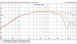
First, in horizontal plane, it's not the width of the baffle that determines it. Its the width in the diaphragm, which in this case is just 15mm, which gives us about 120 deg on 20k.
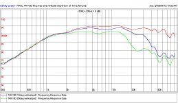
Second, in vertical plane, even though the diaphragm is a lot longer than the wavelength of 20k, the use of acoustical lens, in form of those two foam pads on the face plate, gives us about 20 deg of vertical coverage without any loss highs compared to mids and no loss of flat tone balance.
With proper baffling, the directivity pattern is almost perfect, rounded, figure-of-eight pattern in a horizontal plane, as the ribbon sprays wider that the open baffle arrangement permits, so the baffle rules that plane, governing the figure-of-eight pattern.
In vertical plane, the foam pads rule the situation, and that behaves exactly the same as closed 140-15D.
Measurements attached, but no polar plots, sorry. Too tedious to prepare for publishing but I'm sure you'll figure out the point from these plots.
I also need to say this: thinking that my designs neglect directivity and that my customers are happy with it, couldn't be further from the truth. The whole point of my designs and of my customers desires, revolves around just the opposite. That is why I felt compelled to explain you gents what's this all about.
On that note, model DIPOLE 140-15D can not be used for stacking into line array, it was designed that way, so the accuracy of a near-point source would not be impaired, as well as symmetry of the front-back radiation, which in turn, allows different usage of acoustic lens front and back, so user could fit the directivity to room acoustics in terms of back wall reflections and stereo depth imaging.
As for the prices, I know, they're expensive, but if it was possible to make them cheaper, we'd do it. If any loudspeaker company out there could make a cheaper magnetically shielded, fully front-back symmetrical, open ribbon with this directivity, efficiency and reliability, they would, trust me, and they would have a market for it. The point is that they can't speed it up more that we did. To retain the quality I aim for, it takes a company of five highly skilled people and a few outside machining services to be able to build 50 of those a month, making them only. Once you put things on paper, add shipping and distribution, that what you end up with for a retail price. I can't fight the way the world of economy works, and nobody can. At least we have a choice, and my choice is this: Hopefully, with ever-growing support of our customers that graciously buy our stuff, RAAL will eventually grow into a large company that will improve the manufacturing efficiency and bring out good new products for affordable money. Right now, we are more of an artisan's shop that does things the way any artisan's shop does.
And so on and so forth...I could talk about decisions I needed to make all day long and positively bore you to death!
I wish you a very happy New Year!
I'm off now to "enjoy" some excessive drinking with friends that won't take no for an answer!
Cheers!
Attachments
Not to be a doubting Thomas as I know the RAAL tweeters are highly respected, but I'd really like to see polar plots or at least plots at every 5 degrees vertically and horizontally.
And frankly, when you are asking almost $800 per tweeter I don't think asking for vertical and horizontal polar response plots is too much.
And frankly, when you are asking almost $800 per tweeter I don't think asking for vertical and horizontal polar response plots is too much.
Last edited:
Hi Michael, John, everyone!
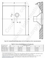
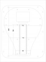
Measurements are done in IEC standard baffle for 8" driver, only the ribbon is flush mounted. Drawing attached for the people that aren't familiar with it.
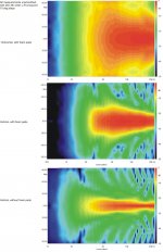
Smoothing is 1/6th oct, brickwall. In any case, CSD plots can't be smoothed out, so they provide clues to what the manufacturer did to make other plots look nice. It will show if it was tampered with too much.
John, I couldn't agree more!
However...You know it better than I do, that polar plot will look as good as it's measurement baffle shape is, as well as driver's position on it.
We also know, that most people while browsing for a driver to buy, just have a glance at the plots and go on. What happens if they spot a big dip at 1k5? Would they contribute it to a measurement baffle size or to the driver? Will they read the fine print and a lenghty explanation why it is there? What will the polar plot look like when that edge diffraction dip start shifting around with measurement angle and even worse, multiply itself by the number of baffle edges as soon as you move the mike away from the dead center?
Naturally, I would like to present the driver at it's best, but in essence, you are actually suggesting that I should design the baffle shape solution, just like you had to do, to yield the best results with your new speaker. But then, would that shape fit the midrange that someone wants to use? Would it fit their taste in design?
Considering the above, and that I would like to make sure that the driver polar plots will not suffer from the baffle shape, the thing I should do is to measure the polar plots in IEC baffle, but then, they wouldn't really look like anything dipole, or at least, like anything that the user would get in their all-too-different baffles than than mine. Would that make me a liar? Would that situation of users getting different measurements by default than what I published, help in increasing or in decreasing the customer satisfaction in the future? Would RAAL drivers remain respectable in that case?
Whatever the thing may be, whether I'm right or wrong, my decision is that upon request, people that can read that data, will get the data acquired with IEC baffle. The success of the completed speaker itself, rests is upon them, so here it is, PDF attached.
The actual driver that has been measured is regular, closed 140-15D. I hope you will trust me on this, but the DIPOLE 140-15D spits out the same graphs in that same baffle.
I hope this helps and I hope it sheds some light on why driver manufacturers aren't jumping ahead and show all kinds of data by default. Too many misconceptions out there and the ones that possess them are the quickest to judge and tell about it.
Cheers!
Measurements are done in IEC standard baffle for 8" driver, only the ribbon is flush mounted. Drawing attached for the people that aren't familiar with it.
Smoothing is 1/6th oct, brickwall. In any case, CSD plots can't be smoothed out, so they provide clues to what the manufacturer did to make other plots look nice. It will show if it was tampered with too much.
John, I couldn't agree more!
However...You know it better than I do, that polar plot will look as good as it's measurement baffle shape is, as well as driver's position on it.
We also know, that most people while browsing for a driver to buy, just have a glance at the plots and go on. What happens if they spot a big dip at 1k5? Would they contribute it to a measurement baffle size or to the driver? Will they read the fine print and a lenghty explanation why it is there? What will the polar plot look like when that edge diffraction dip start shifting around with measurement angle and even worse, multiply itself by the number of baffle edges as soon as you move the mike away from the dead center?
Naturally, I would like to present the driver at it's best, but in essence, you are actually suggesting that I should design the baffle shape solution, just like you had to do, to yield the best results with your new speaker. But then, would that shape fit the midrange that someone wants to use? Would it fit their taste in design?
Considering the above, and that I would like to make sure that the driver polar plots will not suffer from the baffle shape, the thing I should do is to measure the polar plots in IEC baffle, but then, they wouldn't really look like anything dipole, or at least, like anything that the user would get in their all-too-different baffles than than mine. Would that make me a liar? Would that situation of users getting different measurements by default than what I published, help in increasing or in decreasing the customer satisfaction in the future? Would RAAL drivers remain respectable in that case?
Whatever the thing may be, whether I'm right or wrong, my decision is that upon request, people that can read that data, will get the data acquired with IEC baffle. The success of the completed speaker itself, rests is upon them, so here it is, PDF attached.
The actual driver that has been measured is regular, closed 140-15D. I hope you will trust me on this, but the DIPOLE 140-15D spits out the same graphs in that same baffle.
I hope this helps and I hope it sheds some light on why driver manufacturers aren't jumping ahead and show all kinds of data by default. Too many misconceptions out there and the ones that possess them are the quickest to judge and tell about it.
Cheers!
Attachments
Well observed, but there are answers:
The dipole pattern per se can help to avoid/minimise EARLY reflections, which you want to avoid/attenuate in most cases. If you place the dipole at least 3 feet (1 m) away from the nearest room boundaries (which is recommended), the rear reflections are no longer part of the direct field, but become a part of the reverberant field. Some research results of the last decades have shifted views from avoiding most of the reverberant field to allowing most of it IF the content is not altered too much in frequency.
If you prefer to have a DEAD end behind the dipoles, you need to attenuate all frequencies in the same way. Otherwise you can keep this end LIVE and avoid materials at the front wall, which have frequency dependant sound absorption.
Rudolf
That gives a delay of between 5 and 6 ms. At what point do you consider that the direct field ends and the reverberant field begins?
Aleksander, I had to read your previous two posts a couple times to resolve some apparent contradictions between them. But I believe I understand what you're saying and I'd generally agree. The IEC baffle sonograms show somewhat faster vertical roll off than I was expecting but otherwise are a decent match to the horizontal:vertical directivity disparity I was guesstimating. I've worked with other drivers of similar---though not as extreme---aspect ratio (some of which also use acoustic lenses) and it's been my experience the directivity mismatch is both audible and creates challenges integrating with drivers of lower aspect ratio. Also, if you look back at Rudolf's posts earlier in this thread you'll see the basic result is minimizing lobing means minimizing dipole path length and the wide faceplate on the 140 makes such minimization difficult. The resulting dipole peaks and dips are there in the sonograms for folks to reach their own conclusions about.
Personally I'm more interested in a lower aspect, smaller flange solutions. It's not perfect either, but I believe the BG Neo3's currently the leading example.
Personally I'm more interested in a lower aspect, smaller flange solutions. It's not perfect either, but I believe the BG Neo3's currently the leading example.
Thanks for providing some data basis including the measurement conditions.
I agree, dealing with diffraction issues (back closed, OB, IB, nude, IEC) is kind a Sisyphos work
To choose a quasi IB setup for the measurements is clever and certainly "does not make you a liar" - but of course - as mentioned above - its of limited value if the dipole version is intended for nude operation.
But then - OB design isn't *that* easy as it seems - especially not at the very top and bottom end and those going nude usually know what they do (most certainly if they are after a RAAL )
You could try to provide an optimized dipole horn as an option for the RAAL dipole version.
Besids that I'm pretty sure, your plots *at least* will give the endless "foam discussion" a juicy revival...
Michael
I agree, dealing with diffraction issues (back closed, OB, IB, nude, IEC) is kind a Sisyphos work
To choose a quasi IB setup for the measurements is clever and certainly "does not make you a liar" - but of course - as mentioned above - its of limited value if the dipole version is intended for nude operation.
But then - OB design isn't *that* easy as it seems - especially not at the very top and bottom end and those going nude usually know what they do (most certainly if they are after a RAAL
)You could try to provide an optimized dipole horn as an option for the RAAL dipole version.
Besids that I'm pretty sure, your plots *at least* will give the endless "foam discussion" a juicy revival...
Michael
Last edited:
I want to emphazise that my remark in post #58 wasn't critizising the 140-15D in general. It was a comment regarding the specific application as a "nude" dipole tweeter in the context of this thread.
The horizontal polars attached to post #66 suggest that there is no specific "waveguide" element in the driver which could keep it from radiating 180° up to the onset of beaming defined by the ribbon width. Therefore it should largely behave as explained in the general discussion.
I can very well understand that RAAL would not want to show measurements of such behaviour to people who don't understand the peculiarities. But I am quite curious how much of the casing width could be chipped off before cutting into some indispensable material.
Rudolf
The RAAL ribbons are obviously excellent drivers, but I agree with the general sentiment: at $800 each, I'd want to know beforehand that they would exactly fit my application - which is maintaining dipolar regularity (horizontal and vertical) over as wide a bandwidth as possible. I would want to see polar plots of the driver measured without any baffle.
At $50/each, the Neo3 does an almost perfect job (which has mostly to do with its small size). The only thing I could ask for was a lower Fs or more power handling. If the RAALs could do LR4 at 1000Hz, they would be serious competitors because that would make overall speaker design much more flexible. I'd be concerned with a change in timbre as one sits/stands too.
At $50/each, the Neo3 does an almost perfect job (which has mostly to do with its small size). The only thing I could ask for was a lower Fs or more power handling. If the RAALs could do LR4 at 1000Hz, they would be serious competitors because that would make overall speaker design much more flexible. I'd be concerned with a change in timbre as one sits/stands too.
I would want to see polar plots of the driver measured without any baffle.
This I would like it too.
At $50/each, the Neo3 does an almost perfect job (which has mostly to do with its small size).
Almost perfect? Only the polar response maybe.
It's unefficient (therefore requires a line source of 4 or more, raising the cost), the frequency response is all but flat and extended, it is ridiculously low IMO. Not even 22khz.
That gives a delay of between 5 and 6 ms. At what point do you consider that the direct field ends and the reverberant field begins?
We can't possibly define that in ms. And I don't believe that making a real difference between direct and reverberant makes much sense. I very much follow Earl Geddes in his argumentation in this discussion. Look at posts #1, 12, 14. But don't forget that he is selling waveguides.
The only thing that I dislike about his argumentation is the fixation to impulse responses. Newer research into Acoustic Scene Analysis (ASA) suggests that the human brain will follow any real music and real speech much deeper into the "reverberant field" than those clicks or pink noise of most older experiments.
Rudolf
Rudolf, you're reading my mind. The design of the driver was made with having in mind the wish to use it as bare-naked as possible ( I'll tell my opinion of that a bit later). That throws us back to the question of what is the best baffle shape for linear sources like this one, and I, too, have an opinion of that. So...
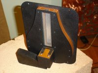
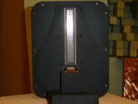
In the attached pictures you can see what the driver looks like from behind.
The pear-shaped structure is the iron yoke that closes the magnetic flux. It was designed in FEM simulation and completely closes the flux with a minimal amount of iron. The iron thickness is 16mm. To that, add 2 + 2 mm of front and back plate.
The front plate is just a mounting flange and it also can be made having the same shape, or completely removed. If removed, the mounting will be a problem, but as it has always been, we make custom front plates without surcharge. If clients start asking frequently for that, I even might decide to redesign it and have it eventually offered as such.
Since this driver is not designed to be used lower than 1.6k, and the mean width of this "pear" allows for about 1k5 cut-off, the driver can be used without this rectangular front plate, without impeding it's low-end response.
That leaves us with this pear shaped yoke, which then plays the role of acoustic baffle, which I believe, is the best possible shape for linear radiators like ribbons. Also, this shape falls in line with this tendency to have double-circle figure-of-eight response extended as much as possible toward highs, but with maintaining the proper low-end (this is a contradictory demand and I'll turn to that later) and without creating too much dips and peaks in the response. It should be a tiny little bit better than naked Neo 3PDR.
Speaking in general now: I mean, c'mon, equidistant edge all around the active surface, are you kidding me?! Show me the naked Neo 3PDR polar plot, horizontal and vertical, please. Better yet, call BG and ask them to send you one. Gee...
later:
Now, to be honest, I never thought that developments of OB design will go towards pushing the ideal, double-circle figure-of-eight all the way up. By definition, you can't have it! Not even with naked Neo3PDR above 2k5. Well, you may get something of a sort, if the active surface size itself is large enough to start beaming, narrowing the kidney, but if it does, it will be frequency dependent and then what? Lobeing and further narrowing toward highs. Double-circle figure of eight is acheivable ONLY below the cut-off frequency of the baffle and that's that.
In short, you can't have double-circle dipole response if your baffle is wider than half of the wavelength at the frequency you are looking at.
Personally, even if it could be done the proper way, I consider it unnecessary, as RT60 times in any room can only have severe nonlinearity and prolongation below 300Hz, and in my book, figure-of-eight (OB woofers) serves as a problem solver in untreated, boomy-bass, rooms by decreasing the excitation of the room modes. I still don't see why it has to be pushed all the way up, as it will only decrease RT60 up there, too, maintaining the RT60 unbalance with low frequencies, solving nothing that OB was originally used for.
To me, whether you have a normal, wide baffle double-kidney or an ideal, double-circle, response of an OB speaker above 3k, isn't something that would make much of a difference, unless you live in one of those ultra-modern, designer apartments that I call "fish tanks" because of the way they sound, because idiots designed them, along with putting the damn kitchen wide open, right in the middle, so you could listen your cutlery rattle with bass and your microwave humming along behind you while you listen to your music waiting on your dinner. If you do live in one of those, my recommendation would be to turn to headphones and forget the high-end speakers based audio altogether, OB or not, and spend more time out of the fish tank.
In any case, you will still have a dipole response all the way up with a null on the side in wide OB's. The main thing is to have that back radiation that reflects from the back wall and gives excellent spatial cues for us to enjoy. A very good reading is Linkwitz's website, and I warmly recommend to anyone that hasn't read it, to do so. A couple of years ago, I've listened to his speaker in his home and from that experience, I can't see what's wrong with having wide baffles. It was THE best stereo imaging I've ever heard in my entire life, and luckily, managed to recreate it or exceed it in my listening room.
Anyway, that was my best shot in making a symmetrical true ribbon tweeter with the best vertical response of all ribbons of the same size out there, with 1k5 cut-off baffle with pretty good acoustical shape, with custom mounting flange when needed. I'm also preparing a small dipole driver, a version of 70-20XR that will be in free sale, not just to manufacturers, which my be better if small pear-shaped baffle ribbon would be better for those design requests mentioned earlier.
Now, as I have a principle of not to use DIYAUDIO forums for business, and things I've already said can be regarded as promotion, I won't be posting any more of anything that has to do with my products. I have my own website for that and any info about new products that I will regard as relevant, will be posted there in due time.
So, when I can join you guys, we can talk principles of operation and such stuff like I tried to do in this post and rattle your cage a little bit
Cheers!
In the attached pictures you can see what the driver looks like from behind.
The pear-shaped structure is the iron yoke that closes the magnetic flux. It was designed in FEM simulation and completely closes the flux with a minimal amount of iron. The iron thickness is 16mm. To that, add 2 + 2 mm of front and back plate.
The front plate is just a mounting flange and it also can be made having the same shape, or completely removed. If removed, the mounting will be a problem, but as it has always been, we make custom front plates without surcharge. If clients start asking frequently for that, I even might decide to redesign it and have it eventually offered as such.
Since this driver is not designed to be used lower than 1.6k, and the mean width of this "pear" allows for about 1k5 cut-off, the driver can be used without this rectangular front plate, without impeding it's low-end response.
That leaves us with this pear shaped yoke, which then plays the role of acoustic baffle, which I believe, is the best possible shape for linear radiators like ribbons. Also, this shape falls in line with this tendency to have double-circle figure-of-eight response extended as much as possible toward highs, but with maintaining the proper low-end (this is a contradictory demand and I'll turn to that later) and without creating too much dips and peaks in the response. It should be a tiny little bit better than naked Neo 3PDR
.Speaking in general now: I mean, c'mon, equidistant edge all around the active surface, are you kidding me?! Show me the naked Neo 3PDR polar plot, horizontal and vertical, please. Better yet, call BG and ask them to send you one. Gee...
later:
Now, to be honest, I never thought that developments of OB design will go towards pushing the ideal, double-circle figure-of-eight all the way up. By definition, you can't have it! Not even with naked Neo3PDR above 2k5. Well, you may get something of a sort, if the active surface size itself is large enough to start beaming, narrowing the kidney, but if it does, it will be frequency dependent and then what? Lobeing and further narrowing toward highs. Double-circle figure of eight is acheivable ONLY below the cut-off frequency of the baffle and that's that.
In short, you can't have double-circle dipole response if your baffle is wider than half of the wavelength at the frequency you are looking at.
Personally, even if it could be done the proper way, I consider it unnecessary, as RT60 times in any room can only have severe nonlinearity and prolongation below 300Hz, and in my book, figure-of-eight (OB woofers) serves as a problem solver in untreated, boomy-bass, rooms by decreasing the excitation of the room modes. I still don't see why it has to be pushed all the way up, as it will only decrease RT60 up there, too, maintaining the RT60 unbalance with low frequencies, solving nothing that OB was originally used for.
To me, whether you have a normal, wide baffle double-kidney or an ideal, double-circle, response of an OB speaker above 3k, isn't something that would make much of a difference, unless you live in one of those ultra-modern, designer apartments that I call "fish tanks" because of the way they sound, because idiots designed them, along with putting the damn kitchen wide open, right in the middle, so you could listen your cutlery rattle with bass and your microwave humming along behind you while you listen to your music waiting on your dinner. If you do live in one of those, my recommendation would be to turn to headphones and forget the high-end speakers based audio altogether, OB or not, and spend more time out of the fish tank.
In any case, you will still have a dipole response all the way up with a null on the side in wide OB's. The main thing is to have that back radiation that reflects from the back wall and gives excellent spatial cues for us to enjoy. A very good reading is Linkwitz's website, and I warmly recommend to anyone that hasn't read it, to do so. A couple of years ago, I've listened to his speaker in his home and from that experience, I can't see what's wrong with having wide baffles. It was THE best stereo imaging I've ever heard in my entire life, and luckily, managed to recreate it or exceed it in my listening room.
Anyway, that was my best shot in making a symmetrical true ribbon tweeter with the best vertical response of all ribbons of the same size out there, with 1k5 cut-off baffle with pretty good acoustical shape, with custom mounting flange when needed. I'm also preparing a small dipole driver, a version of 70-20XR that will be in free sale, not just to manufacturers, which my be better if small pear-shaped baffle ribbon would be better for those design requests mentioned earlier.
Now, as I have a principle of not to use DIYAUDIO forums for business, and things I've already said can be regarded as promotion, I won't be posting any more of anything that has to do with my products. I have my own website for that and any info about new products that I will regard as relevant, will be posted there in due time.
So, when I can join you guys, we can talk principles of operation and such stuff like I tried to do in this post and rattle your cage a little bit
Cheers!
Attachments
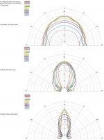
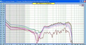
Although I've posted it elsewhere, it sounds like it might be appropriate here - the attached graph is the polar response of a neo3pdr, measured by me. The graphs are 0-15-30-45-60-90 degrees horizontally, with no baffle, and have almost an ideal dipolar response. The only blip is around 8kHz, and that can be mostly fixed by adding foam edging to the driver. JohnK has designed a waveguide that is also very successful. I've built and listened to a handful of dipole tweeters, and they've all had errors - but personally, I don't hear the 8kHz deviation. Most other dipolar tweeters have errors in the 1kHz-5kHz range, where our ears are most sensitive, and the error is very obvious. I've used the Neo3pdr crossed as low as 1700hz, LR4, and not had problems.
Aleksander, I really appreciate your thoughtful replies, and I admire the excellent construction of your tweeters. I hope you continue to be part of this discussion. I think we are all mature enough here to realize and accept each others biases, and still be part of a meaningful discussion.
Aleksander, I really appreciate your thoughtful replies, and I admire the excellent construction of your tweeters. I hope you continue to be part of this discussion. I think we are all mature enough here to realize and accept each others biases, and still be part of a meaningful discussion.
Attachments
Last edited:
I think all the discussions ultimately come down to this. Does 'true dipole' response matter in the top octave or two? How much does it matter?To me, whether you have a normal, wide baffle double-kidney or an ideal, double-circle, response of an OB speaker above 3k, isn't something that would make much of a difference
Thank you for your contributions to this thread, especially the measurements. It's nice to finally see some charts. Maybe they've been posted elsewhere, but this is the first time I'm seeing them.
That's only something one can really answer by building it and A/Bing. Which is tough. But phon curves are loosely equivalent from 5-20kHz and 1kHz-100Hz so I'd expect importance roughly comparable to directivity in the lower mid/upper woofer range, though somewhat reduced due to lower PSD and high frequency hearing retraction with aging.Does 'true dipole' response matter in the top octave or two? How much does it matter?
Can't specifically help with that as I own the non-PDR version. But what software are the 140 sonograms from? I've been seeing them pop up of late and wouldn't mind picking up the measurement capability if it's affordable to do so---I could cobble something together with exporting data from HOLMImpulse to Matlab but it'd be a bit of a hassle.Show me the naked Neo 3PDR polar plot, horizontal and vertical, please.
Not very much. Maybe not at all. What matters more is smooth transitions at the crossover(s), without "bloom" and with minimal vertical lobing, for smooth power response. It is altogether too easy with speaker design to fixate on "pretty patterns" or one particular "feature" and sacrafice other, often more important, issues in the pursuit.I think all the discussions ultimately come down to this. Does 'true dipole' response matter in the top octave or two? How much does it matter?
Thank you, gents, I appreciate your welcome. I'll try to be useful, even though I'm coming from omnidirectional with OB woofers camp.
Of course, biased we all are, but we shouldn't forget that we're dealing with objectively measurable stuff and objectiveness will have to unleash us from of our biases once we accept the physical truth and compare it to definitions we claim to follow.
So let's talk principles and definitions we so easily throw around.
For example, cuibono, you do have a fairly nice result, but just at a first glance. It isn't anything near of what it should be.
Let's analyze those results in depth, and someone tell me if I'm wrong. I may be and/or the measurements may be wrong.
Definition: If I remember correctly, almost an ideal dipole response must have about -6 db at 45 degrees, -12 dB at 60 degrees and at least -24 at 90 degrees at all frequencies compared to dead on-axis. Correct me if this is untrue, I'm rusty in math department.
Measured result: That "almost ideal" you mentioned should read "+6 dB to the goal", which is double the energy. Doubling things, or adding 100%, is not a near miss. This happens between the crossover frequency to 6k, above which, things get rough.
Ideal dipole response does not account for such lobeing that manages to make 3dB more on 30 and 45 deg and +1dB at 60 deg. than on axis, turning a response with octave wide -6dB dip on axis into a response with 3dB peak at 60 degrees. That is about 12 to 15 dB more than the goal. That is quadrupling things, which again, can't be called a near miss.
Consequence:
The first reflection off the side wall, which is between 30 to 60 degrees, depending on the room size and speakers-listener layout within it, will on average between 6k to 10k, receive the same energy as your listening position. If anything gives spatial cues, that is this frequency band and if anything, dipole shouldn't do that.
Verdict:
Considering that below 6-7k, dipole is not nearly as fully functional, we can call it a moderate success to the goal that has been set. What we have here is a double-kidney equally obtainable with a wide baffle.
Considering that, centered at 8k, we have a cloverleaf pattern of two lobes front and two back, and depression of 3dB on axis, and that on average it has equal energy dispersion up to 45 degrees, falling off only 11 to 12 dB on average at 90 degrees, we can call it a failure.
9k is a very interesting point, as we have equal energy distribution with only 8-9dB drop at 90 degrees. I also suspect that there is a 45-ish degrees phase-shift break there that allows the 90 deg. 9k peak not to be canceled properly with back radiation. It may be due to slots resonance and/or spacing. Examination of anything that may fall into 38, 19 or 9.5 mm with driver's construction will provide a cause to problems between 6 to 10k.
If it is just edge diffraction related, it is correctable with a baffle/frame of enough width to allow for transposing the dip below the crossover frequency and framing the driver in such a way that the face plate becomes flush with frame front and back surface. If the baffle/frame does not have equidistant edges to the active driver surface (slots area), it may be possible to use the lesser width than what the crossover frequency suggests.
Considering that above 13k we have just simple beaming, but working exactly the dipole below baffle cut-off should, we can consider it a full success.
As far as the room interaction is concerned, all of the above is easily corrected with absorbers on side walls at the point of first reflection. If you don't already have them, that shouldn't be hard to do, so try it out and see what you should be aiming for. Let us know is it better. Follow the speaker-listener-room layout that Linkwitz suggested.
As for the audibility of -6dB at 8k, you certainly hear it, just don't know how to pinpoint it's attributes. A very good exercise is to use headphones and try tampering with any EQ from any media player on your computer.
One of these days, I'll make measurements with this dipole tweeter of mine without front plate and we'll see what is it like. I suspect it will turn out to be allota work to try to correct for anomalies if they appear so I'll give report about it and the correcting methods. Right now I'm too busy, but I'll do it, eventually.
Cheers,
Can't specifically help with that as I own the non-PDR version. But what software are the 140 sonograms from? I've been seeing them pop up of late and wouldn't mind picking up the measurement capability if it's affordable to do so---I could cobble something together with exporting data from HOLMImpulse to Matlab but it'd be a bit of a hassle.
Got it from cuibono.
it's Clio. Their latest feature is balloon plot. Very pretty!
dewardh, I second that.
- Home
- Loudspeakers
- Multi-Way
- On the directivity of dipole tweeters