But for the diy'ers, for <1-2kw, it is just not needed, since parts you can buy this days can be used in half bridge at higher powers then maybe 20 years ago
Yeah, I have a pending 2kW full-bridge PSU project for years. I've got all the necessary parts but now that I have the time again, I'm seriously considering to buy an extra cap and just go for half-bridge. When I was thinking about building it, I thought I'm going to save some room with the single cap but it's not the case. On the other hand the bigger the cap(s) lesser the ripple noise is, so it won't hurt. Just need a bigger project box.

Luka , how are you.Glad to see you are still monitoring this thread. I think its time to start using some of the new devices that are cheaper in these designs, in some cases you can find IGBT's that are suitable. I use them in my hard switcher's, another thought if you are going to use a gate drive consider adding a small transformer for house keeping and putting controller IC on secondary side, sure helps with feedback.when using smd you can place gate drive very close to mosfet gate, to make things more compact consider multiple daughter boards,one for feedback,current control and shutdown for faults all this can be on one small board and another for gate drive close to mosfets.use pfc and go to LLC,ZVS the only draw back is magnetics, split bobbins for diy hard to get but of course you can make your own.With good layout rarely need parts on bottom of board..., I forgot another reason for multiple daughter boards it makes it easy to use SS for mother board therefore smaller, better air flow.Stewin, in the thread for 1kW LLC Christi provided schematic for 500watt LLC without pfc, might help you..
Last edited:
You don't even have to buy another cap. For a long time, if you are not on 120v system and you are not planing to use it ever on it, you can get away with one main cap, and instead use two smaller ones, let's say 1u, to connect other side of transformer to the cap side, first one being main switches. I think stewin has the schematic showing this. And if not using really old components, you can have pretty high switching freq. which do translate to using smaller cores. And using something like PFC in front of your supply will decrease your need for big primary cap (which takes a lot of space) and reduce your primary ripple away. Yes your "simple" project is not so simple anymore, but for one time build, hell what more do you need?Yeah, I have a pending 2kW full-bridge PSU project for years. I've got all the necessary parts but now that I have the time again, I'm seriously considering to buy an extra cap and just go for half-bridge. When I was thinking about building it, I thought I'm going to save some room with the single cap but it's not the case. On the other hand the bigger the cap(s) lesser the ripple noise is, so it won't hurt. Just need a bigger project box.
Hello dear sir, it's been long time.Luka , how are you.Glad to see you are still monitoring this thread. I think its time to start using some of the new devices that are cheaper in these designs, in some cases you can find IGBT's that are suitable. I use them in my hard switcher's, another thought if you are going to use a gate drive consider adding a small transformer for house keeping and putting controller IC on secondary side, sure helps with feedback.when using smd you can place gate drive very close to mosfet gate, to make things more compact consider multiple daughter boards,one for feedback,current control and shutdown for faults all this can be on one small board and another for gate drive close to mosfets.use pfc and go to LLC,ZVS the only draw back is magnetics, split bobbins for diy hard to get but of course you can make your own.With good layout rarely need parts on bottom of board..., I forgot another reason for multiple daughter boards it makes it easy to use SS for mother board therefore smaller, better air flow.Stewin, in the thread for 1kW LLC Christi provided schematic for 500watt LLC without pfc, might help you..
Using IGBT's would probably be my go to device this time around. I will remember when Eva was all against using mosfets, since price was higher then BJT's and you can really do a lot with BJT's. Now better option would probably be IGBT's.
Secondary side controller? maybe... but then again, there is so much data for compensation and feedback in general that it shouldn't be necessary.
Using SMD would be great, far more easy then THT this days.
And I would be nice to try something like LLC or ZVS, maybe not for first project like this, but for the next for sure. But maybe this is more complicated for people indeed because of magnetics.
Funny how back then I was looking for AC to DC supply, how they work, how to make them and such, to day is other way around
full circle I guess Hi Luka. Thanks for the tip. It is going to have an active PFC running on 400V. Accordingly the filter is also 400V and 2.2mF. So do you mean if I put 2x smaller caps in series after the big filter to split the supply voltage? Isn't that going to produce a lot of ripples?
I would like to see the best PFC design to build too for a single channel 400 watt amp (8 ohm) I would do a good PCB and share it IF either or both Luka ans Chas1 would bless it even a little...Thanks I am leaning toward Full Bridge, if that is possible but what ever is Best for DIY.....
Last edited:
pfc
1.I wouldn't bother with PFC for 400W nor would I waste money for FB when HB will do fine and if you need supply for single amp take a look at 1kW LLC thread where Christi has posted a schematic for 500W LLC converter and on the web you can find many designs for a supply to fit this requirement. You will still need to supply the requirements for the amp,Voltage and Current requirements.
I would like to see the best PFC design to build too for a single channel 400 watt amp (8 ohm) I would do a good PCB and share it IF either or both Luka ans Chas1 would bless it even a little...Thanks I am leaning toward Full Bridge, if that is possible but what ever is Best for DIY.....
1.I wouldn't bother with PFC for 400W nor would I waste money for FB when HB will do fine and if you need supply for single amp take a look at 1kW LLC thread where Christi has posted a schematic for 500W LLC converter and on the web you can find many designs for a supply to fit this requirement. You will still need to supply the requirements for the amp,Voltage and Current requirements.
I would even for 400w, but I would probably do it only if I could salvage core from some old PC supply... well I did for my, so core was one problem less. Rest of the pcb and components are nothing, few hours if that of work. Try to find some old PC supply, the ones that were ~3x volume of today's standard size supply's. That one had PFC and "normal" supply in it, but it kinda looked as server supply, maybe because it was.1.I wouldn't bother with PFC for 400W nor would I waste money for FB when HB will do fine and if you need supply for single amp take a look at 1kW LLC thread where Christi has posted a schematic for 500W LLC converter and on the web you can find many designs for a supply to fit this requirement. You will still need to supply the requirements for the amp,Voltage and Current requirements.
But for one 400w amp, not.. waste of money, power that will be drawn will be pretty small, but you can always go for biggest you can build, just because you can and to learn.
Either way, if you need help with something, do tell, we are here (still
) to help400? wouldn't be 380v enough, so you can get way with 400v caps?Hi Luka. Thanks for the tip. It is going to have an active PFC running on 400V. Accordingly the filter is also 400V and 2.2mF. So do you mean if I put 2x smaller caps in series after the big filter to split the supply voltage? Isn't that going to produce a lot of ripples?
http://www.diyaudio.com/forums/atta...-smps-need-help-gtg-lp-ps-ver-1-schematic.pdf
I mean like so: one big 400v cap, and two in series. Look at how they are connected to transformer and fets
Thanks to you both for sharing
I want to run this in the USofA so I will have 110 input voltage...
But I am thinking any PC supply would be dual voltage..
I would have to find a old PC supply of at least 1200 watts and pull the parts..
Do supplies of that size have a requirement of PFC?
Thanks 4 the insights
I want to run this in the USofA so I will have 110 input voltage...
But I am thinking any PC supply would be dual voltage..
I would have to find a old PC supply of at least 1200 watts and pull the parts..
Do supplies of that size have a requirement of PFC?
Thanks 4 the insights
Well some do have pfc and are universal input, some are switch selectable 110/220 or so.Thanks to you both for sharing
I want to run this in the USofA so I will have 110 input voltage...
But I am thinking any PC supply would be dual voltage..
I would have to find a old PC supply of at least 1200 watts and pull the parts..
Do supplies of that size have a requirement of PFC?
Thanks 4 the insights
No you don't have to find that powerful supply, my was 350/400w only, yet inductor is pretty big, all I have for now is that inductor core cross section is about 2.3cm^2. And as I noted on my site, I tested it over 1kw for few seconds, since diodes were at that stage getting hot to fast
I'm not sure, I don't think it is, but could be wrong.
I would think you might list your requirements, you can get away with 120VAC without a voltage doubler and you might be able to use the IRFP250 for the Switch that should give you about +/- 50volts @5 Amps with no problem a inductor of about 30uH in each output with 2 1000uF caps on each output bypassed with a couple of 100nF try for fsw of 75kHz which the average core set from PC supply should handle, Most PC supplies are a multi output two transistor forward converter with a flyback for housekeeping, the primary is about 40 turns(20+20) so the first winding 20T of primary then the secondaries and the last primary is left.all have some form of PFC, mostly passive, the newer ones might use active PFC.?? if output to low change fsw to 80kHz.
Last edited:
hi guys eagle is very simple . electric noob and others have many tutorials on you tube.
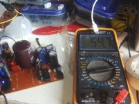
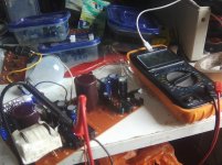
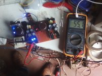
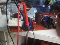
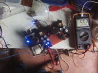
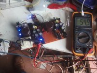
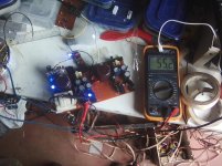
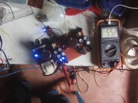
i thank GOD i tested the smps it is working great , the gate drive with transistors works very well. i used 3ohms load at +/-55 vlts ucd class d . the irf 740 smps power fets did not warm at loud playing (i did not mount on heat sink) .i listened about 2 hours loud music all was well.
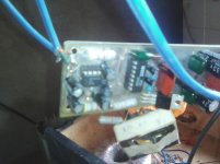
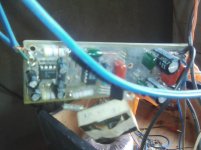
i chose to use 450vlts caps instead of dual 200vlts because i find many in scrap circuits in my area. here are the photos of my project. i have made many boards. the below is my first photos experience .
the gdt is ee19 1:1 15turns the switching freq is 47khz i.e rt=15k ,ct=1nf ,discharge=33ohms
i thank GOD i tested the smps it is working great , the gate drive with transistors works very well. i used 3ohms load at +/-55 vlts ucd class d . the irf 740 smps power fets did not warm at loud playing (i did not mount on heat sink) .i listened about 2 hours loud music all was well.
i chose to use 450vlts caps instead of dual 200vlts because i find many in scrap circuits in my area. here are the photos of my project. i have made many boards. the below is my first photos experience .
the gdt is ee19 1:1 15turns the switching freq is 47khz i.e rt=15k ,ct=1nf ,discharge=33ohms
Attachments
-
 IMG_20160524_091313_1.jpg625.1 KB · Views: 621
 -
 IMG_20160524_091310_1.jpg643.1 KB · Views: 580
 -
 IMG_20160524_091257_1.jpg401.1 KB · Views: 548
 -
 IMG_20160524_091257.jpg419.7 KB · Views: 536
 -
 IMG_20160524_090943_1.jpg667.2 KB · Views: 510
 -
 IMG_20160524_091250.jpg444.8 KB · Views: 140
 -
 IMG_20160524_090936.jpg649 KB · Views: 149
 -
 IMG_20160524_090936_1.jpg686.1 KB · Views: 132
 -
 IMG_20160524_090927.jpg704.6 KB · Views: 141
 -
 IMG_20160524_090930.jpg626.5 KB · Views: 153
Last edited:
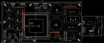
hi all more half bridge boards version for higher power handling .they have more banks in capacitor boards are hp 20cm x 15cm and mp 20cm x 10cmideas and suggestions are highly welcomed .have fun and post your builds
Attachments
-
gtG hp ps ver 1 bottom components.pdf15.3 KB · Views: 196
-
gtG hp ps ver 1 top components.pdf44 KB · Views: 207
-
gtG hp ps ver 1 pcb top.pdf15.5 KB · Views: 188
-
gtG hp ps ver 1 pcb bottom.pdf70.7 KB · Views: 209
-
gtG hp ps ver 1 schematic full.pdf36 KB · Views: 366
-
gtG mp ps ver 1 pcb top.pdf14.6 KB · Views: 211
-
gtG mp ps ver 1 pcb bottom.pdf62.3 KB · Views: 246
-
gtG mp ps ver 1 components bottom.pdf15.2 KB · Views: 263
-
 full top components.png67.2 KB · Views: 347
http://www.diyaudio.com/forums/powe...ll-bridge-smps-need-help-130.html#post4721747
this smps works perfectly with irf740 and irfp460lc gdt is ee16 12turn primary and 12turns both secondaries switching frequency used was 45khz. the above 2 fets worked well without mounting them on a heatsink just warmed abit when used load at loud spl note: i did not mount on heatsink . but when i used irfp460a or igbtIRG4PC50/40 they produced a lot of heat within seconds of operation . when increased the switching frequency the igbt ran abit cooler but heat was still too great even though i mounted on heatsink.
photos http://www.diyaudio.com/forums/powe...ll-bridge-smps-need-help-132.html#post4725507
Last edited:
IGBT GATE DRIVE
The drive circuit might need some modification for IGBT, the gate source resistor value is very important 10 ohms seems high.I am attaching photo of gate drive for both MOSFET and IGBT that I am using might solve your problem with IGBT , I have not checked datasheet for the device you are using but will take a look there could be other problems. like the device might not be for suitable for fsw you are using.
The drive circuit might need some modification for IGBT, the gate source resistor value is very important 10 ohms seems high.I am attaching photo of gate drive for both MOSFET and IGBT that I am using might solve your problem with IGBT , I have not checked datasheet for the device you are using but will take a look there could be other problems. like the device might not be for suitable for fsw you are using.
Attachments
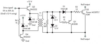
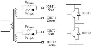
Checked datasheet, should work but gate resistor value might need to be lower try 5 ohms and increase as needed but no more than 10 ohms, the IGBT is a voltage device and the turnoff time is important, the photo's of the methods I used seem to work very well but I had to experiment with the values for the devices I used.
- Home
- Amplifiers
- Power Supplies
- Offline full-bridge SMPS… need help