Are you sure you get 80 volts with 8 turns of secondary?what is switching frequency(fsw)?I would think you might need upwards to 14t per secondary,Also the scheme for the fan and aux 12 volts, you can get that from the same 3 or fours turns off secondary I would think.By using two small diodes you can get both +/- aux supply, make sure you fuse those outputs as a short downstream will be reflected into the primary as shorted turn.you don't need bridge for 12 volt aux, if you use it wind 8 turns and center tap , filter both neg and plus sides of bridge and you get bipolar 12 or what ever you needs be sure and fuse the outputs.I do the transformer calculations again, for half bridge you should be able to lower primary turns depending on fsw, check out chapter 3 of Pressman Switching Power Design, If you need a little more power increase the fsw a little say from 50khz to 60 or 70kHz no need to change transformer but check Bmax first.
Last edited:
thanks chass 1 for quick reply.
i have changed the ct and rt to 4n7 and 2k2 which makes the sw to be abt 64khz . the turns i used the dimmonis transformer calculation tool .i used 7 0 7 turns for secondary and 23turns for primary . which gave me abt +/-43vlts . i needed to drive the etjagle ultra simple class d.
i have changed the ct and rt to 4n7 and 2k2 which makes the sw to be abt 64khz . the turns i used the dimmonis transformer calculation tool .i used 7 0 7 turns for secondary and 23turns for primary . which gave me abt +/-43vlts . i needed to drive the etjagle ultra simple class d.
Its good to use a proven design as a template,but I am glad to see you did your own modification's for your requirements as many people might construct the supply expecting to get the results indicated on the sheet without doing calculations and then disappointment sets in and changes are made that are not needed resulting in added expense as well as danger to downstream load.

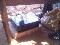
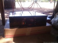
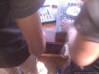
thanks chas 1 for the support i am realy greatfull.photos of the latest smps project .

Attachments
Last edited:
I was surprised with the results of simulations of atlk6 on a win7 machine with LTspice ver20x, they were needless to say very different than my system (useless) so until I can return to office and check on my win7 pro laptop please report any problems in any platforms.
Hi all! Help me please.
I made 2 boards triell 3200, but i have some problems. I do this SMPS - XP-5000, on this post: http://www.diysmps.com/forums/showth...design)/page80
What better transformer for this? ETD 49 or ETD 59?
These transformers work at what frequency? Can i increase frequency for bigger power, and how?
Sorry for my bad English...
my Email- CDJKuznec@ya.ru, if it is necessary for convenience.
Welcome SDZhKuznets
this post, fixed http://www.diysmps.com/forums/showth...design)/page80
that in the scheme triell 3200 you can view or a reference
this post, fixed http://www.diysmps.com/forums/showth...design)/page80
that in the scheme triell 3200 you can view or a reference
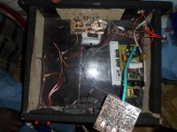
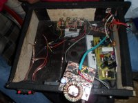
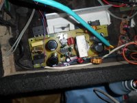
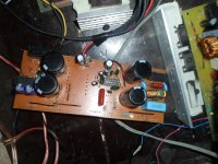
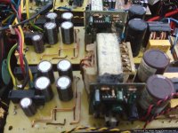
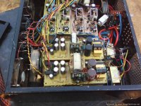
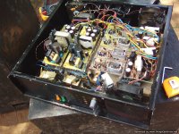
hi all . my pictures of my half bridge power supply . i used bd139 and 140 to drive the gdt because ic sg 3525 failed some times when driving gdt directly. one smps was +/- 75vlts dc for midrange and +/-85vlts for subwoofer .amp was ucd class d
Attachments
-
 IMG_20150624_122631_1-Optimized.jpg121.3 KB · Views: 259
 -
 IMG_20150624_122631-Optimized.jpg157.6 KB · Views: 291
 -
 IMG_20150624_122438_1-Optimized.jpg156 KB · Views: 328
 -
gtG smps lp small schematic.pdf38.4 KB · Views: 449
-
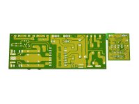
gtG smps lp small pcb top .pdf15 KB · Views: 250
-
gtG smps lp small pcb bottom .pdf50.3 KB · Views: 285
-
gtG smps lp small components full.pdf43.3 KB · Views: 280
-
gtG smps lp small components clear.pdf41 KB · Views: 311
-
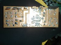
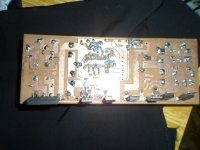
 gtG smps lp small bottom.jpg234.4 KB · Views: 401
 -
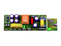 gtG smps lp small.jpg290.5 KB · Views: 418
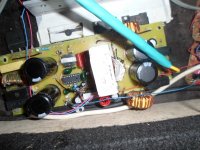
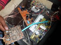
more photos on the project .
Attachments
-
 IMG_20150529_115422-Optimized.jpg130.2 KB · Views: 189
 -
 IMG_20150529_115415-Optimized.jpg123.9 KB · Views: 467
 -
 IMG_20150529_115350-Optimized.jpg161.8 KB · Views: 497
 -
 IMG_20150529_115309-Optimized.jpg73.9 KB · Views: 516
 -
 IMG_20150529_115208-Optimized.jpg198.6 KB · Views: 565
 -
 IMG_20150529_115102-Optimized.jpg160.2 KB · Views: 585
Based on the 3A fuses I see on the +/- outputs.... I am assuming your loads are no greater than 2 Amps per rail....
I consider this low power converter...60W to 100W range....
Much easier for you to make the Push-Pull converter ...less parts and no high side driver...all low side GND referenced drivers...you can probably use the same chip ....
If you are bent on using the Full-Bridge.. then use a gate Driver chip between your chip and the FETS.... IR makes some that have ISO for Hi and Low side driving in Bridge config...
i meant gdt gate drive transformer .
btw i have been using my gdt design without any issue .but just wondering will this method of driving fets.improve the perfomance. i use irfp 460. at 70khz
btw i have been using my gdt design without any issue .but just wondering will this method of driving fets.improve the perfomance. i use irfp 460. at 70khz Attachments
I use gate drive because ir 2110 when smps fails ir fails .but with gate drive fets are the only things to replace
Looking at the complex secondary side oft GDT I would prefer the silicon half-bridge drivers. It is true that a failing power-MOSFET normally breaks down between drain and gate thus destructing its gate driver. But there is a simple solution to avoid this: You insert a coupling capacitor into the gate line that is capable to block supply voltage, something like 10nF/400V=. To restore DC-component you bypass this cap with 220kOhm/0,5W. You will never have to replace the driver-IC after that!
hi voltwide thanks for the contribution. my transfo gate drive works good with irf740 and irfp460 but on igbt,s the igbts gets hot on powering up even without a load .i wanted to try the above because the square wave at the gate is clean. maybe it will work better with fets or work with igbt.
btw have you tried your design with success it??
Looking at the complex secondary side oft GDT I would prefer the silicon half-bridge drivers. It is true that a failing power-MOSFET normally breaks down between drain and gate thus destructing its gate driver. But there is a simple solution to avoid this: You insert a coupling capacitor into the gate line that is capable to block supply voltage, something like 10nF/400V=. To restore DC-component you bypass this cap with 220kOhm/0,5W. You will never have to replace the driver-IC after that!
btw have you tried your design with success it??
Based on the 3A fuses I see on the +/- outputs.... I am assuming your loads are no greater than 2 Amps per rail....
I consider this low power converter...60W to 100W range....
Much easier for you to make the Push-Pull converter ...less parts and no high side driver...all low side GND referenced drivers...you can probably use the same chip ....
If you are bent on using the Full-Bridge.. then use a gate Driver chip between your chip and the FETS.... IR makes some that have ISO for Hi and Low side driving in Bridge config...
i use 8 amps fuse per rail ,because 4 amps is small and it fails when the amp is pushed hard. i,ve used transformer gate drive on fets without any issues. but i wanted to go full bridge to attain more power on smps.
- Home
- Amplifiers
- Power Supplies
- Offline full-bridge SMPS… need help