I don't belong to diysmps,as for your voltage adjust and other sections of your design use sources you can find on the web or simulate the circuits in question until you get them to behave and try to stay away from power grabbers like zener regulators that require more passive components(heat generators).A good free simulator is LTspice and its free the learning curve is short and has a excellent forum.I will post a simulation of your design shortly.Check your design before PCB layout, I would make the first one slightly larger to make it easier to find problems and allow room for modifications,I would layout a farm of pads along one side or a corner for design changes of circuits for prototype..small signal stuff.
thanks chas 1 i am thankful for your reply .pls include a voltage adjust .although my smps is working o.k after using zeener in my feedback. i am very great full for more improvement . my transformer turns ratio are
>>primary 21 - 0 -13turns,
>> secondary is 9 turns 0-9 turns
>>Aux for fan and IC control 4turns
The other small former
>>Current protect former small from an old ups i see the primary turns are 3turns, the secondary are many, i assume they are 100 turns
the main core etd 44 It works perfectly with more turns on the primary side, my previous experiments with transformer gate-drive showed that it used less current on the mains if i used more primary turns but you can simulate and tell me if i am wrong

the corrected schema according to how i changed my board after etching the first one
Forced Gifting
Attachments

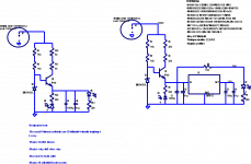
thanks chas 1. pls post pdf file some components are not visible. i will modify and post the schematic thanks again and GOD bless you .
Forced Gifting
Forced Gifting
If you have LTspice and would like simualtion files I will post them,also on voltage adjust
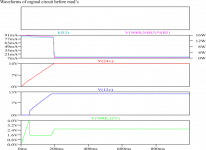
zener's are best choice for you now,I have simulated the circuit in your schematic I think there is a better solution,will post later.While not necessary you might want to include small inductance after output caps 30 to 50 uh wound on a single core onev and connected in both +/- outputs with polarity reversed.
zener's are best choice for you now,I have simulated the circuit in your schematic I think there is a better solution,will post later.While not necessary you might want to include small inductance after output caps 30 to 50 uh wound on a single core onev and connected in both +/- outputs with polarity reversed.
hello dear friends
my name is Hadi from iran
i want to creat my own car amplifier but can not to creat smps for that.
i see in diy site you do that in past.
can you please help me to creat a good smps?
sory for my bad english
very thanks for your helping.
have a nise day dear friends.
my name is Hadi from iran
i want to creat my own car amplifier but can not to creat smps for that.
i see in diy site you do that in past.
can you please help me to creat a good smps?
sory for my bad english
very thanks for your helping.
have a nise day dear friends.
Thank
I see this befor
This smps can not handel my amp
I use 6 chanell amp
B80 from apex
I need +-20vac 15a
there is "no" limit on how big you can make it, there is shown basic, "concept design" if you will... most work the same way and you only need to know basic operation, so that you can scale it up or down for your needs
Yes that specific supply probably won't be for you, but that was the goal of the designer. Anyway... this supply will not give AC out of it, but already DC, so you must know DC voltage you would need
Yes that specific supply probably won't be for you, but that was the goal of the designer. Anyway... this supply will not give AC out of it, but already DC, so you must know DC voltage you would need
car amp smps
Hi luka
i know i need dc voltage for my amp
i have super ultra fast diod.
i mean my exit transformer in smps must can handel +-20VAC 15A
this is my minimum need
please help me to create this smps
do you have a good shematic for this push pull smps?
thanks
there is "no" limit on how big you can make it, there is shown basic, "concept design" if you will... most work the same way and you only need to know basic operation, so that you can scale it up or down for your needs
Yes that specific supply probably won't be for you, but that was the goal of the designer. Anyway... this supply will not give AC out of it, but already DC, so you must know DC voltage you would need
Hi luka
i know i need dc voltage for my amp
i have super ultra fast diod.
i mean my exit transformer in smps must can handel +-20VAC 15A
this is my minimum need
please help me to create this smps
do you have a good shematic for this push pull smps?
thanks
the link offered on post #1189 by chas 1 is a good power supply you can add more output fets for more power of the power supply. the only limitation is that it does not have overcurrent. protection
http://forcedgifting.com/?ref=stewin
http://forcedgifting.com/?ref=stewin
are you looking for the 110/230v input voltage or 12v like car?Hi luka
i know i need dc voltage for my amp
i have super ultra fast diod.
i mean my exit transformer in smps must can handel +-20VAC 15A
this is my minimum need
please help me to create this smps
do you have a good shematic for this push pull smps?
thanks
hi hadighorbani also tr this forum
http://www.diyaudio.com/forums/car-audio/31614-making-car-amplifier-smps-tl494-dc-protection.html
Forced Gifting
http://www.diyaudio.com/forums/car-audio/31614-making-car-amplifier-smps-tl494-dc-protection.html
Forced Gifting
i creat that in 2 monthe ago but dose not workingthe link offered on post #1189 by chas 1 is a good power supply you can add more output fets for more power of the power supply. the only limitation is that it does not have overcurrent. protection
Forced Gifting
may be have error in bd139 and bd140
whwn i conect amp to output smps, the output voltage down to 5 volt
- Home
- Amplifiers
- Power Supplies
- Offline full-bridge SMPS… need help