Hi all,
I am building a 4kW hard switching full-bridge SMPS for 230VAC (400VDC) that will drive 8xHGTG7N60A4D IGBTs at 100kHz.
http://www.datasheetcatalog.org/datasheet/fairchild/HGTP7N60A4D.pdf
I've never built SMPS at this caliber thus I'd ask some advices what category of flyback diodes would be optimal for this application? I'm also having issues with space within the box and on the large heatsink so I prefer radial diodes.
The IGBTs are going to be driven by 2xIR2110. Is that ok or shall I use more advanced gate drivers that can be mounted on heatsink?
Many thanks
Kind Regards
Tony
Last edited:
600V, SMPS Series N-Channel IGBT with
Anti-Parallel Hyperfast Diode
The IGBTs are going to be driven by 2xIR2110. Is that ok or shall I use more advanced gate drivers that can be mounted on heatsink?
Should be no problem power-wise.
Switching 2x40nC at 15V VGE at fsw=100kHz correspond to 0.12W of losses per an IGBT gate. This losses are spread between gate resistors and a gate driver, the higher the gate resistors, the less stress to the IR2110's.
Ah ok I have the wrong datasheet on my PC that's what I was looking which is for HGTG7N60A4 and not HGTG7N60A4D but the one I've ordered is the latter as well as the datasheet linked here. Thanks for the headsup. ")
Am I ok with 50ohm gate resistors at each gate?
Many thanks again.
Am I ok with 50ohm gate resistors at each gate?
Many thanks again.
Am I ok with 50ohm gate resistors at each gate?
Agh, the same old good question... and there is no simple answer.
If you understand the switching losses mechanisms, like plain transition losses, diode reverse recovery losses and current tail losses you'll definitely determine the right value youself by looking at your 'scope. If you don't want to go too deep than the thermometer on heatsinks is your friend here.
If I were in your shoes, I'd stay with 25 ohms cited in the datasheet for the start, the IGBT datasheets are generous enough to directly show switching energies (Eon, Eoff).
All you have to do to estimate switching losses is scale them (linearly) to your VCE and IC values and multiply them with switching frequency.
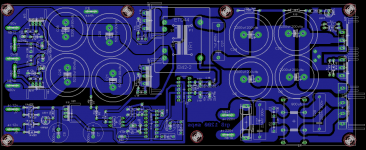
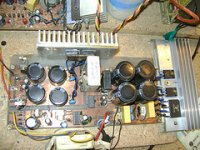
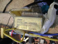
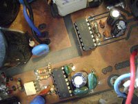
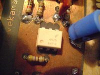
hi luka and all i've finally completed my smps and tested it for 2 months although i am using a small aux former it is cool and power full thanks guys for your support.
http://farm8.staticflickr.com/7141/6524827599_ce30830e42_m.jpg

http://farm8.staticflickr.com/7141/6524827599_ce30830e42_m.jpg
Attachments
-
 offline bottom.png78 KB · Views: 1,038
 -
 6524815663_3c27496bfd_m.jpg33.9 KB · Views: 517
 -
 6524839577_bb80aa8c11_m.jpg22.2 KB · Views: 339
 -
 6524840295_993afaff32_m.jpg22.2 KB · Views: 950
 -
offline halfbridge high power pcb artwork s .zip458.4 KB · Views: 505
-
offline art work.zip611.7 KB · Views: 541
-
offline halfbridge high power schema values.pdf30.9 KB · Views: 630
-
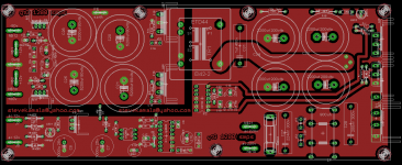 offline top.png71.7 KB · Views: 985
 -
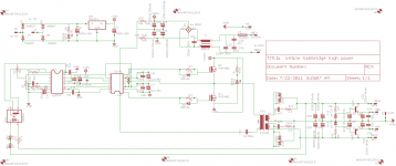 offline schema.png31.7 KB · Views: 1,005
 -
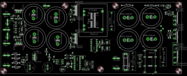 offline components.png54 KB · Views: 1,002
Last edited:
more photos
Attachments
-
 6524815663_3c27496bfd_m.jpg33.9 KB · Views: 248
 -
 6524828343_2dd46c3e04_m.jpg29.6 KB · Views: 163
 -
 6524830575_c3aa97452a_m.jpg27.8 KB · Views: 138
 -
 6524833639_6c7f6d7f38_m.jpg23.8 KB · Views: 146
 -
 6524838919_5dc91df3bd_m.jpg22.1 KB · Views: 148
 -
 6524841719_daab087ba2_m.jpg22.4 KB · Views: 151
 -
 6524835073_4ec67138cd_m.jpg23.9 KB · Views: 235
 -
 6524841023_8bd777e7a5_m.jpg25.4 KB · Views: 237
 -
 6524840295_993afaff32_m.jpg22.2 KB · Views: 483
 -
 6524823533_906b6e1860_m.jpg25.4 KB · Views: 245
Last edited:
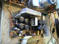
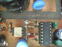
thanks njec car ,luka, eva , mzzj ,n channel chas 1, xclipse, and every one who participated on this forum . though most parts i recycled from old parts of scrap machines due to lack of availability of parts. the circuit is working fine. GOD bless you all for your efforts. a link to photos
Flickr: stevekamala's Photostream
Flickr: stevekamala's Photostream
Last edited:
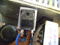
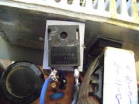
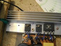
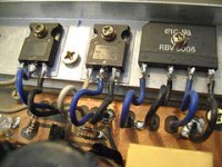
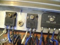
one question, why did you place fets like you did, and use wire to connect them, while they are on heatsink, like you show on the picture?
And I see you have double sided pcb, that should be easy to connect them via pcb... this part I don't like too much, and I hope you will explain why you did this
Edit: not fets, but output diodes
And I see you have double sided pcb, that should be easy to connect them via pcb... this part I don't like too much, and I hope you will explain why you did this
Edit: not fets, but output diodes
Last edited:
Good job Steven!
@luka, it appears to me it was easier to solve the mechanical mounting of the heatsink horizontally. It also looks like it was his first project so I wouldn't measure it with very strict engineers' eyes. For a hobbist it is a prime job with CAD work, etching, etc, not to mention he used surplus parts.
So I would say Steven: thumbs up mate.
@luka, it appears to me it was easier to solve the mechanical mounting of the heatsink horizontally. It also looks like it was his first project so I wouldn't measure it with very strict engineers' eyes.
For a hobbist it is a prime job with CAD work, etching, etc, not to mention he used surplus parts.So I would say Steven: thumbs up mate.
And this is my point, he done so good job with the pcb, he sure could do with mounting the diodes and fets too. Someone has to be critical, to push him even further on, making one even better. As far as i am concerned, I couldn't be more happy to see this thread help someone else beside me!
I can't remeber what was the performance of Stewin's PSU, but as for the core he used I presume it is above 70W, which means here in the EU the PFC would be mandatory for that PSU. I don't know the regulations in the US though but PFC is always recommended so IMHO it always worths the hassle.
As for the 110V, if you're lazy you can simply half the number of primary turns and adjust the frequency if necessary (and mind the core and FET temperatures!). Although I would strongly suggest using a transformer calculator to find the correct values.
As for the 110V, if you're lazy you can simply half the number of primary turns and adjust the frequency if necessary (and mind the core and FET temperatures!). Although I would strongly suggest using a transformer calculator to find the correct values.
This might help:
http://www.its.caltech.edu/~mmic/reshpubindex/papers/buckwalter.pdf
note:No voltage doubler ( low costs IRFP250 used,no pfc).If turns were calculated correctly
then Vbulk max would approach 385VDC@220VAC max (270VAC) a good value for pfc output.
chas1
http://www.its.caltech.edu/~mmic/reshpubindex/papers/buckwalter.pdf
note:No voltage doubler ( low costs IRFP250 used,no pfc).If turns were calculated correctly
then Vbulk max would approach 385VDC@220VAC max (270VAC) a good value for pfc output.
chas1
Last edited:
SAFeTY
Looks like you spent good time designing your SMPS, But seems to me it suffers badly from safety issues, witch visually didn't pass for me.
Like, but not limited to creepage distances, Isolation, etc..
Good Luck
a link to photos
Flickr: stevekamala's Photostream
Flickr: stevekamala's Photostream
Looks like you spent good time designing your SMPS, But seems to me it suffers badly from safety issues, witch visually didn't pass for me.
Like, but not limited to creepage distances, Isolation, etc..
Good Luck
- Home
- Amplifiers
- Power Supplies
- Offline full-bridge SMPS… need help