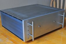
Dead silent!
......and a very good build.
no need for fan , if you make slot at (both) circumference(s)
stone bbq .... yup , heaven technique ...... sausages are pretty much worst thing to prepare on ....... any other (real ) meat is allowed to develop full flavor palette , when roasted equally and not choked with smoke
stone bbq .... yup , heaven technique ...... sausages are pretty much worst thing to prepare on ....... any other (real ) meat is allowed to develop full flavor palette , when roasted equally and not choked with smoke
ZM,
I take a quick look on the top plate, I can put 1/4" standoff to get better ventilation but the bottom plate as part of the structural, spacers going to weaken the whole enclosure. May be drill more holes on both top and bottom plates. I don't like slot because I don't have CNC mill. If by handheld power tool that will need a complicated jig to accomplish. Let me think about to see that what I can come up with a simple way to make a fixture that can tackle the slots.
I take a quick look on the top plate, I can put 1/4" standoff to get better ventilation but the bottom plate as part of the structural, spacers going to weaken the whole enclosure. May be drill more holes on both top and bottom plates. I don't like slot because I don't have CNC mill. If by handheld power tool that will need a complicated jig to accomplish. Let me think about to see that what I can come up with a simple way to make a fixture that can tackle the slots.
ZM advice taken
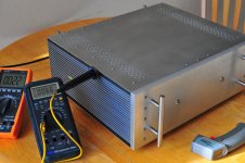
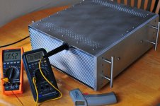
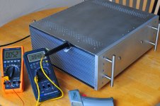
5/16"-24 nuts were installed last night as suggested by ZM. There are 7mm gap create between the top and bottom plates. I fired up the amp this morning with one temp probe attached to the fin of the heatsink the other air temp probe placed inside the enclosure to monitoring the temperature. The temperature rise to 52-53C, inside temp up to 40C after 3 hours of idling. I feel more comfortable while listen to music without the concern for the temperature.
Thank you ZM!
Attachments
I have limited space for a amp, so I wonder if the 3U, 300 or 400 mm Mini Disipante would be big enough to handle the heat from the M2? If so, I could put the power supply in a sepparate enclouser and stack them. I've searched this forum, and the Modushop homepage, but can't find any comments or answers, so I'd appreciate any input.
Thanks!
//Ronny
Thanks!
//Ronny
Thanks Zen Mod!
I haven't decided anything yet, just considering possibilities. Mono blocks is definitly a possible way to go! I have a pair of 24V/500VA toroids lying around. I know the voltage is to high, but if i could some how use those it would be a bonus. Otherwise I'll get a pair of 2x18V.
I haven't decided anything yet, just considering possibilities. Mono blocks is definitly a possible way to go! I have a pair of 24V/500VA toroids lying around. I know the voltage is to high, but if i could some how use those it would be a bonus. Otherwise I'll get a pair of 2x18V.
I have limited space for a amp, so I wonder if the 3U, 300 or 400 mm Mini Disipante would be big enough to handle the heat from the M2?
I run an M2 including PSU 2x18V in a Mini Dissipante 3U 300mm with heatsinks at 52 deg C.
The whole contraption sits on 26mm feet and I added 3mm spacers between both top and bottom plate and the heatsinks.
I understand it's been more than a year to promote the schematic, but the diodes D1 ... D3 are not connected wrong ??? These diodes should ensure bias voltage for IRFP's and as they are connected now, I do not see how it would ensure bias voltage.
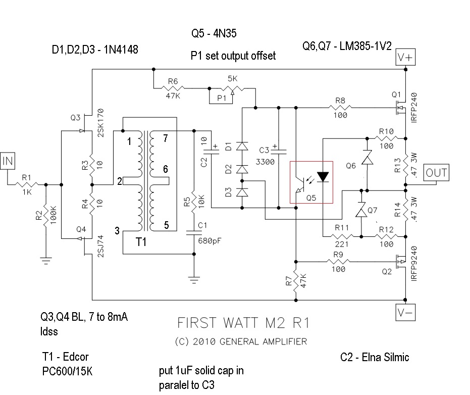
explained somewhere in start of the thread ...........where I also wrote that it gave me a headache to decipher it
they're here to clamp driving node to rails , in case some idiot is feeding amp with gargantuan signal
so , just imagine input signal of 12Vpp .......
also - try to search forum for my (amateurish) try of explaining biasing mechanismus
they're here to clamp driving node to rails , in case some idiot is feeding amp with gargantuan signal
so , just imagine input signal of 12Vpp .......
also - try to search forum for my (amateurish) try of explaining biasing mechanismus
I understand how it works "biasing mechanismus", actually using Q5, but the Q5 to be nearly saturated then you have the voltage on the resistors R14 and R15 to be quite large - such a voltage is understandable especially to strictly follows operation in Class A of IRFP's. Great problems of this circuit is that, I think, at power supply up, until it automatically adjusts the bias of Q5, might as transistors IRFP bear a considerable shock current (in the situation when power load is connected to output).
Use of that transformer in reaction circuit and VAS, It reminds me of some old amp schematics of the 70's. I would not really agree with this complication because it has several disadvantages compared to using an present VAS.
Use of that transformer in reaction circuit and VAS, It reminds me of some old amp schematics of the 70's. I would not really agree with this complication because it has several disadvantages compared to using an present VAS.
Heat Sink TME
I am not sure about dissipation to use this ones.
RAD-C26260/200 STONECOLD - Radiator: geprägt | TME Germany GmbH - Electronic components
No other information available.
Any help welcome, than i can finally finish the M2.
Thanks ElFishi for sharing.I run an M2 including PSU 2x18V in a Mini Dissipante 3U 300mm with heatsinks at 52 deg C
I am not sure about dissipation to use this ones.
RAD-C26260/200 STONECOLD - Radiator: geprägt | TME Germany GmbH - Electronic components
No other information available.
Any help welcome, than i can finally finish the M2.
- Home
- Amplifiers
- Pass Labs
- Official M2 schematic