I've run into an interesting problem with my LM3886 amplifier. I get quite serious amounts of hum whenever the volume control on the amplifier is at anything other than 0 or full volume, when plugged into my diy DAC. This doesn't occur when plugged directly into a iPod, and interestingly it occurs even when the DAC is not plugged in! If the signal cable is not connected to anything it's fine, but just plugging it into the DAC without any power cable going into the DAC triggers it. Plugging in the DAC and turning it on doesn't affect the level of the hum.
I've also noticed that when turning the amp off, the hum stops immediately, while the music keeps playing for a few seconds. This seems weird to me, I would expect both to continue while the caps deplete.
I've tried floating the amp's ground by just not connecting it to main ground, but it didn't help. I can upload some pictures of its internals if need be.
1. Leave the amp ground connected, for safety.
2. Either move the on/off switch away from the untwisted input cables, or twist the living daylights out of the input wires and the ac switch wires.edit 2..On further inspection, the switch is on the far side of the chassis? Put it next to the xfmr.
3. Isolate at least one of the RCA's from the chassis so that you do not form a loop that is directly under the power switch(?). Preferably, isolate both from chassis. This doesn't however, stop the coupling to the switch lines. edit: It seems that gootee said all plastic case...in that case, just get that switch moved to the transformer side of the chassis, but still twist the ac runs. It will also help to put the rcs'a as close as is reasonable to each other. Also, use shielded input wires, and twist them to each other as well to prevent input ground loop coupling within the chassis.
Please post a picture of the unit with the volume controls added.
Oh, also, as a general rule, twist all wire pairs or triads which send/receive current.. This includes the ac mains of the transformer, as well as the common with both legs of the transformer secondary, this would mean three wires twisted together between the toroid and the board.
And, a question..why did you put the heatsink fins horizontal? Will you be adding a fan later?
Cheers, John
ps..gootee...you're a geek.. Faraday's law of induction indeed...nerd..
")
you sound like someone else I know...me...
Last edited:
if there is a ground loop with the transformer and earth , a working solution is to put a small resistance .5 - 10 R, depending on the design, on the ground line , also in one or both of the ground cables going to the amplifier module, (also 2 reverse diode in // for more protection in case the resistor burns. )
This gives you three emplacements to control ground loops. But judging from the level of noise you get, very high if I remember, my best suspicion is a faulty RCA socket ground or positive, in my last pre-amp that was the problem, please try it and tell me if it improves.
Lastly there is the 0.01 capacitor trick: put it in // with the incoming audio signal wires or outgoing wires from the amplifier.
if there is a ground loop with the transformer and earth , a working solution is to put a small resistance .5 - 10 R, depending on the design, on the ground line , also in one or both of the ground cables going to the amplifier module, (also 2 reverse diode in // for more protection in case the resistor burns. )
This gives you three emplacements to control ground loops. But judging from the level of noise you get, very high if I remember, my best suspicion is a faulty RCA socket ground or positive, in my last pre-amp that was the problem, please try it and tell me if it improves.
Lastly there is the 0.01 capacitor trick: put it in // with the incoming audio signal wires or outgoing wires from the amplifier.
1. As the OP stated, there was significant hum even when the source equipment was not plugged into the line. You solution would therefore not work.
2. Your solution is very dangerous. It violates code in the united states. I do not know what code is where the OP is. On this side of the pond, a failure on the hot line must be capable of clearing the overcurrent device, be it breaker or fuse. Here, a 10 ohm would pull only 12 amperes, which would not clear the breaker, leaving the equipment energized. This is a situation where I would never wish to be able to say I told you so.
Cheers, John
<snipped>
Cheers, John
ps..gootee...you're a geek.. Faraday's law of induction indeed...nerd..
you sound like someone else I know...me...
Aw shucks. That might be the nicest thing anyone's said to me yet today [OK, maybe longer than that. Thank you for bestowing that badge of honor. Unfortunately, I have to let it rust before wearing it, since I'm now relatively old and have allowed my hard-won engineering and mathematical knowledge, skills, and abilities to become mostly rusty, or actually more like a long-neglected formerly-deep-water ship channel that's become not much more than silted-in shallows. Such a pity. What about the port?!]
Coincidentally, I just received an order from Amazon that includes "A Treatise on Electricity and Magetism", both Vol 1 and Vol 2, by James Clerk Maxwell, plus "A Student's Guide to Maxwell's Equations", by Daniel Fleisch, which looks excellent, and two other Maxwell reprints: "The Dynamical Theory of the Electromagnetic Field" and "An Elementary Treatise on Electricity". I also couldn't resist getting "The Strangest Man: The Hidden Life of Paul Dirac, Mystic of the Atom". [Remember the Dirac Delta function? It's the convenient infinitely narrow (in time) "pulse", of infinite amplitude, but with an enclosed area of unity. Very handy, if I recall correctly, for things like the impulse response of dynamic systems. Probably actually invented before Dirac "discovered" it, by Fourier. But Dirac was definitely "the geeks' geek".] Anyway, regarding the first two books I mentioned, I simply cannot believe that I (and every other EE student) didn't have them while studying EE. He covers virtually "everything". Now I simply must also acquire all of Michael Faraday's original writings!
Cheers,
Tom
Last edited:
That sounds like there's some connection between the primary and secondary that the 60 Hz goes through. Use an ohmmeter to double-check that there's infinite (or at least many megohms) resistance between the primary and secondary(ies). You can unplug the power cord, turn on the power switch and measure between each plug blade and each of the secondary wires....
I've also noticed that when turning the amp off, the hum stops immediately, while the music keeps playing for a few seconds. This seems weird to me, I would expect both to continue while the caps deplete.
It could be the interwinding capacitance as discussed in post #16. This seems a little less likely to me, unless there's something about the wiring together of the ground connections in your amp that makes it particularly sensitive to it.
Your other statements also indicate the problem may be solely in your amp. Get an RCA cable, plug one end into your amp input, and with a screwdriver short the signal and ground at the other end, thus shorting your input. Does this generate the hum just as the DAC does? If so, this definitely points to the wiring in your amp. It would be helpful to see both a schematic and a mechanical wiring diagram.
What does the ground of the RCA inputs go to? Disconnect RCA grounds, and connect each ground to the "bottom" (ground) connection of the corresponding channel's potentiometer.
I think that updated, detailed photos of the inside of the amplifier are long overdue. Let everyone see exactly how the thing is wired and it will be much more likely that you will get the solution. You have the interest of some very-capable people who want to help you. Now you just need to follow through and give them the means to try to do it. These guys are really good. But don't keep them waiting for too long.
The photo doesn't show the volume control, which was a latter addition.
Did you also have the hum issue before adding the volume control or only afterwards?
Does the volume pot have a metal case that is not yet connected to ground?
Did you daisy chain the ground from the input via the pot to the PCB for convenience instead of using separate ground wires from the PCB to the input and to the pot?
Aw shucks. That might be the nicest thing anyone's said to me yet today [OK, maybe longer than that.
Um, Tom? If geek and nerd are the nicest things you've been called in a while, you may need new friends..
Books...
Me, I prefer the really challenging titles.
MP3 for Dummies.
Macs for Dummies.
C++ Neural Networks for Dummies.
Physics of Semiconductor Devices for Dummies.
Control System Design for Dummies..
Quantum Chromodynamics for Dummies..
NEC for Dummies.
(if one looks hard enough, one can notice a trend there...)
Calculus De-mystified..(don't know how that snuck in there..)
Jackson, Becker, Rojansky, Shadowitz, Kittel, Sze, ...same ol, same ol...
Cheers, John
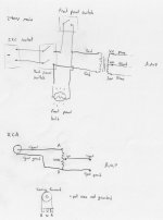
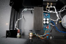
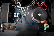
I've created a diagram showing the current case wiring scheme. I've also attached some up-to-date pictures.
From what I've read I should implement a "star" grounding scheme. I'm not sure exactly how to do this due to the plastic case. Exactly which parts in the attached diagram should be tied earth?
From what I've read I should implement a "star" grounding scheme. I'm not sure exactly how to do this due to the plastic case. Exactly which parts in the attached diagram should be tied earth?
Attachments
Star grouding means tying the different grounds together at a single point in a way that no loops exist. That point doesn't necessarily have to be on a (metal) case, though.
But since this whole thing is on just a single pcb, I don't see how you could have a ground loop. I assume there's just a single GND on that pcb to which both PSU- and amp-sections connect.
EDIT: I can't really judge from the pictures, but both LM3886 are electrically insulated from the heatsink, aren't they?
Why aren't both pots connected the same way to the pcb? From what I can see in the picture, on the pcb there are three holes for each of the pots to connect to, two of which have markings beside them. The white and blue wire are connected to the positions with the markings, while the orange looks to be connected to the unmarked position... Didn't you swap something on one channel (and perhaps with it a signal-GND)?
Last edited:
Actually, star grounding means that each "ground" point in your circuitry has its own separate ground-return conductor going back to the power supply ground (which is often between the main filter capacitors' "ground" ends).
In practice, they don't all have to be separate. But you definitely don't want your amplifier inputs' reference-ground points sharing any length of ground-return conductor with any ground-return conductors that might carry any fast-changing or large currents.
Why not? Because every conductor has distributed inductance and resistance and currents flowing in them therefore induce voltages that effectively appear back at the non-power-supply-ground ends of those conductors. The "ground" voltage there is then changing. It's somethimes called "ground bounce".
If one of the non-ground ends of a shared ground-return conductor is at the "ground" end of a resistor connected to your amp's input, then those induced voltages would be arithmetically summed with your input signal's voltage! That would be "a bad thing", especially when you consider that the inductance portion of a conductor's impedance induces voltages that are proportional the the rate-of-change of the ground-return current, rather than its amplitude (as it would be for the resistance portion of the impedance).
Cheers,
Tom
P.S. Star grounding, and the grounding scheme for a circuit's operation, aren't usually about connecting anything to an actual earth ground. "Circuit grounding" usually only has to do with connecting ground returns and ground voltage-reference points back to the power supply "ground". But you will also need to connect the circuit ground to the earth ground, for safety.
Last edited:
zip
P.S. Star grounding, and the grounding scheme for a circuit's operation, aren't usually about connecting anything to an actual earth ground. "Circuit grounding" usually only has to do with connecting ground returns and ground voltage-reference points back to the power supply "ground". But you will also need to connect the circuit ground to the earth ground, for safety.
Indeed, these two must not be regarded as the same thing. IMO opionion it would be better to call circuit ground "common".
But if you mean by earth ground the same as protective earth (PE), i.e. the GND pin (or PE pin) of a mains socket, then I disagree with your last statement, and would advise against connection of circuit ground with PE.
It depends on the construction of the appliace whether it needs to be connected to PE or not (actually I should write "can" and "must not", at least in Europe).
Appliance class I devices have fundamental insulation only. The metal casing of these can be connected to PE. These can be recognised by the earth symbol and a three conductor power cord.
Appliance class II devices have either fundamental insulation combined with extra insulation or reinforced fundamental insulation. These devices must not be connected to PE. Recognisable by the double square symbol and a two conductor power cord.
In audio equipment, usually only (professional) equipment with symmetrical in- and outputs are constructed as a class I appliance with PE. In that case the X of the XLR-sockets are connected to the casing (and thus PE).
In consumer audio equipment with asymmetrical circuits constructed as a class II appliance, PE MUST NOT be connected. Not only because regulations say so, but to prevent interference with audio circuits as well. That's why they come with a two conductor power cord only.
In electronics factories PE is called "dirty earth" for a reason. All ESD protected areas (EPA) are connected to a separate earthing system dubbed "clean earth". PE and clean earth interconnect at one point only.
The two attached diagrams are (partly) in Dutch, but you'll get the picture (schakeling = circuit; voeding = power supply; metalen behuizing = metal casing).
The subscripts read:
Class 1: A class 1 audio device with symmetrical in- and outputs, the optional gnd lift may only be present when a class 2 insulated transformer is installed.
Class 2: A class 2 audio device with asymmetrical in- and outputs.
Attachments
our common mis-use of the word ground is very confusing.Indeed, these two must not be regarded as the same thing. IMO opionion it would be better to call circuit ground "common".
But if you mean by earth ground the same as protective earth (PE), i.e. the GND pin (or PE pin) of a mains socket, then I disagree with your last statement, and would advise against connection of circuit ground with PE.
I agree that specific names for each return wire be used, but we cannot change the habits of 6billion people.
Audio Ground is a perfectly good name for the voltage reference in an audio amplifier.
Safety Earth is a good name for the chassis connection in audio gear.
Protective Earth is the correct name for the third wire going back to the distribution board, (in the UK), I don't know how universal it is world wide.
PE must be permanently connected to Safety Earth.
All exposed conductive parts MUST be connected to Safety Earth.
All the gear we build MUST CONNECT Audio Ground to Safety Earth.
We are not competent to design, build, test and guarantee ClassII equipment.
Last edited:
- Status
- This old topic is closed. If you want to reopen this topic, contact a moderator using the "Report Post" button.
- Home
- Amplifiers
- Chip Amps
- Odd grounding problem