Disclaimer
First of all I want to present myself as a beginner audiophile mostly with theoretical knowledge rather than real experience. All materials discussed in this article is subject to change and dosen't mean to be ultimate truth. This project of mine has a goal to make a person on a budget happy. Any suggestions, advices, aiming in right direction, corrections and kind words are more than welcome! ")
Second of all must admit that I need a little help to take this project to the finish line. Let's make it together and keep all discussion positive.
A little history
It all started when I did research on the interent when was about to buy multimedia speakers for my home PC. Few days after then I foun numerous forums for audiophiles, head-fi, diyaudio, headphiles, doctorhead, player to name a few. And not to mention mamny blogs with tons of information about DACs, preamplifiers, power amplifiers, speakers, headphones and other audio equipment. All in-between history is all about learning theory, some DIY practice, other peoples mistakes and making my own.After few years of research I finally have time and money to make my humble home headphone desktop system. And hope that this project can become a standart in such DIY budget segment. And as mentioned in diclaimer, only if you will help me to solve some little problems, maybe this project can help make people on a budget like me very happy.
The componets of system
All componets described below are already ordered and on their way, so changes should be small as possible and better shouldn't be at all.
Here is a list of additional componets
Transformers:
1) dual 18v 5W for analog supply both The Wire and PGA2320
2) 9v small ~3W for digital supply both MCU controller and PGA2320 digital part
Voltage regulators:
1) For analog part The Wire and PGA2320 will get separate regulators on LM317 and LM337
2) For digital part of PGA2320 and MCU controller single LM317 regulator
Other componets - different connectors are a matter of taste and needs, I use simple 3.5mm, 6.35mm and RCA jacks. Case will be plastic, you can find a lot of these for electronic projects.
Here is a list of componets used in this project:
DAC - ODAC from NwAvGuy on es9023 dac chip with Tenor te7022 USB receiver
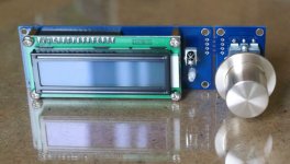
Volume regulation - PGA2320 from AptAudio, DCV01 PGA board
and MCU01 controller unit with remote control
Headhone amplifier - The Wire from OPC
Information about project
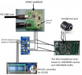
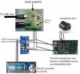
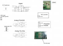
Here is a general view plan of my small projectQuestions and problems
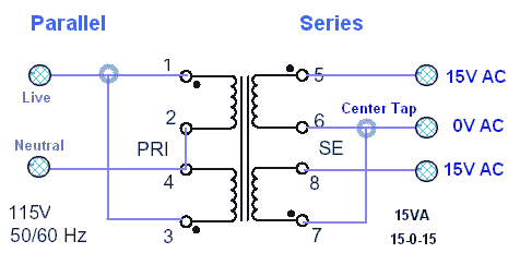
1) The first problem is dual transformer connection to voltage regulator. The thing is, my regulators have input AC-GND-AC. Each regulator has one full wave bridge rectifier as seen on picture. And there are two kinds of connection with transformer, parallel and center tap, described here. First way you have only two AC wires, the second way you have AC-0-AC scheme. So the question is which way is better? Should I use first or second, in other words if GND input on regulators will be free, wouldn't this cause any problems?
2) The problem I am not familiar with is source selection.
Ok, here we go. We have ODAC --> PGA2320 --> The Wire. I want my project to be versatile so preamp and separate headphone amp functions are welcome. For these functions there will be many connectors. So basically ODAC will have 3.5mm line out and also connection going to PGA2320. But to use PGA also as a preamp I want to solder 3.5mm and double RCA on its input and 3.5mm and double RCA on its output. I presume this way project will be able to work as a Standalone DAC, Variable output DAC, Preamp and Headhone amp.And the question is for example: Preamp function - if I have some other DAC and AMP to listen and connect it to PGA2320 input via connector (3.5mm or RCAs) can I leave ODAC and The Wire turned on? Wouldn't there be interference and will the signal go thru PGA without any problems? Same thing and question for headphone amp function, wouldn't it interference with ODAC turned on?
Don't know how to formulate question correctly. Does this project need a source selector, or I just can solder few connectors on one input and output of PGA2320?Conclusion
For this ODAC + PGA2320 + The Wire project I wanted to have the best bang for buck and price/performance, price/quality ratio. As you can see all parts of system are relatively cheap for their specs. Hope with few corrections this project can cross the finish line with succes. Attachments
-
 project 1.jpg175.5 KB · Views: 109
 -
 $(KGrHqZ,!lIE1F3PZbojBNcdD+fk8w~~_3.JPG73 KB · Views: 1,537
 -
 !BuBL8hg!Wk~$(KGrHqEOKjMEvNj,JMY1BL-i4qBmnQ~~_3.JPG122.2 KB · Views: 1,487
 -
 amp15-b2.jpg35.9 KB · Views: 1,432
 -
 mcu01-8.jpg30.2 KB · Views: 1,409
 -
![odac closeup[4].jpg](/community/data/attachments/263/263012-c3e184907b967334ccbf202395845ce8.jpg) odac closeup[4].jpg101 KB · Views: 1,469
odac closeup[4].jpg101 KB · Views: 1,469 -
 SE-SE%252520AMP.JPG101.4 KB · Views: 1,456
 -
 project 11.jpg54.7 KB · Views: 1,534
Last edited:
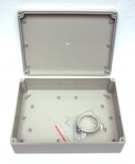
There are some reasons to use NEMA box. Plastic is easy to work with and ground is not a problem as I am planning to do just as you suggested. Also thinking of connecting the transformer secondaries in center tap scheme for the analog supply. This way ground plane should be ok.
Attachments
Actually I find metal easier to work with. Plastic has a lot of weird things you have to be aware of. For example, make sure you run your drill press on a very low setting using water to drill out the holes in the plastic to avoid burning through it.
Looking at your picture, your not incorporating the ground in the equation. I realize you may think it's not an issue, but when you are dealing with power supplies it is.
Thinking about it further, the other problem you are going to deal with is heat dissipation. That is one reason why most/all preamps/amps use metal cases. I think with your design you will need to install a small fan or two in the rear of the case.
Can you please describe or draw the grounding scheme for this project? I didn't catch what you are talking about.
As for the heat dissipation, all components are low power and good efficiency, nothing to worry about. In worst scenario I will cut some ventilation holes above hottest parts in top cover of the case. I bet fans will be unnecessary here.
As for the heat dissipation, all components are low power and good efficiency, nothing to worry about. In worst scenario I will cut some ventilation holes above hottest parts in top cover of the case. I bet fans will be unnecessary here.
You'll still need heat dissipation of some type. Your power supply will generate a ton of heat. This is one of the reasons why computer power supplies have fans. Vents will still be needed irregardless. Rather than holes I would mill out small vents, 1" by 1" using a 1/16 or 1/8" mill bit. You can get the bit for a dremel, but you would need a holder.
I actually don't have autocad installed right now, as my hard drive just died and I had to get a new one. I don't have the power supply specs, but I think you would need one off the VI input, and one off the VO input (probably V6 in your picture). Ground is just a ground. It goes to the earth. Same thing with the neutral line. Neutral lines in houses are just connected to the grounding lug. Still without a ground in this, if your neutral line goes bad, your electronics / power supply will suffer!
I actually don't have autocad installed right now, as my hard drive just died and I had to get a new one. I don't have the power supply specs, but I think you would need one off the VI input, and one off the VO input (probably V6 in your picture). Ground is just a ground. It goes to the earth. Same thing with the neutral line. Neutral lines in houses are just connected to the grounding lug. Still without a ground in this, if your neutral line goes bad, your electronics / power supply will suffer!
I'd consider a metal shroud (or metal case) of some sort that is grounded to the negative terminal on the headphone jack. That will aid in noise rejection.
As for the AC wiring, I don't see a need to use a center-tap or wall ground connection. Is there any component that needs or wants a ground or the center-tap pin? Maybe the controller or volume control... but double check on that because the other parts don't need a ground circuit that's connected to the wall.
As for the AC wiring, I don't see a need to use a center-tap or wall ground connection. Is there any component that needs or wants a ground or the center-tap pin? Maybe the controller or volume control... but double check on that because the other parts don't need a ground circuit that's connected to the wall.
I would also consider using a 4 pole connection all round, no minis; including reterminating your headphones if possible. even though you have the single ended amp here, headphones and stereo audio in general benefit to having a dedicated return for each left and right connection. I would use a dual secondary transformer rather than center tapped, just because thats how the wire is set up and these are connected in series at the PSU anyway so effectively gives you a center tap, you can use either, but do not presume you need the center tap for ground.
Your star ground for analogue signal should be at the ground of the psu that powers the wire and possibly I would connect the analogue output ground from the ODAC here as well, then have a separate digital ground for the MCU etc and connect this and the analogue ground at one point and one point only, to the IEC earth ground
@ethanolson:
sure it does not need safety ground to function, but it should still be used for the main ground. he can break potential loops by simply connecting the main ground to SE through a low ohm resistor or thermistor for loop breaker.
look at the system grounding thread/article on here for illustration
Last edited:
Thanks qusp for answer. So you mean to connect transformer secondaries in parallel to get double current with the same voltage? You see I have a problem, no earth ground at IEC in my home. So basically I need to deal with just insides of the case.
There is a scheme at the internet with connection between transformer and LM317 LM337 bipolar supply.
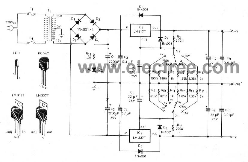
That is what I'm talknig about.
And a few questions about common ground. Will the ODAC use PC ground from USB line, wouldn't it be enough? And if I connect analog The Wire and PGA2320 ground, wouldn't this cause interference, noise, decrease in performance?
And BTW with center tap PGA and The Wire will have a common ground.
There is a scheme at the internet with connection between transformer and LM317 LM337 bipolar supply.
That is what I'm talknig about.
And a few questions about common ground. Will the ODAC use PC ground from USB line, wouldn't it be enough? And if I connect analog The Wire and PGA2320 ground, wouldn't this cause interference, noise, decrease in performance?
And BTW with center tap PGA and The Wire will have a common ground.
Attachments

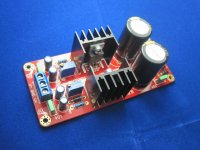
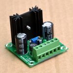
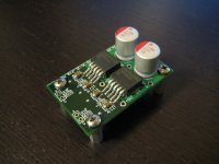
Here is the power related componets I have for this project. Remember, I have no earth ground at home. I know it is bad, but have nothing to do with it.
Can someone draw how should I connect them to maintain a proper grounding techniques?

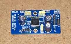
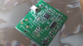
About the ODAC. Here is a close up picture and I see no ground connectors here (besides audio signal of course).
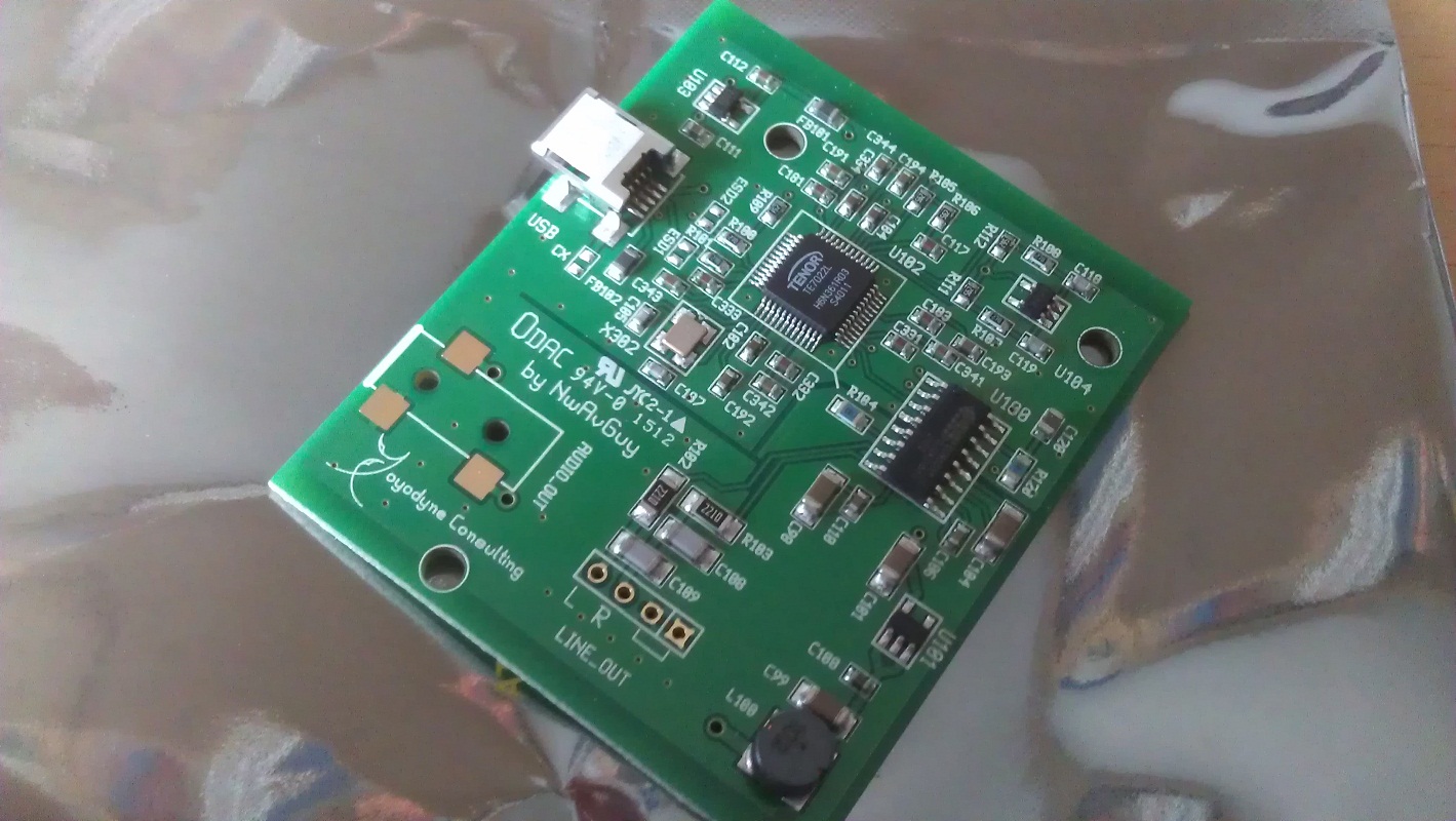
Can someone draw how should I connect them to maintain a proper grounding techniques?
About the ODAC. Here is a close up picture and I see no ground connectors here (besides audio signal of course).
Attachments
look at the PSU you have for the wire, it has 4 holes yes? nothing parallel just connect the 4 wires, in the same order they exit the transformer from left to right from the 2 secondaries, done. this actually puts them in series, not parallel as the 2 middle wires will be connected at this point on the PCB to make a center tap. but do not connect that point also to ground of the wire, just leave it, the center will be effectively at about the same reference voltage as ground as it exists in this circuit, but that point in the middle before the bridge there will have quite a bit of noise. the line that goes down the middle of your schematic there is the ground line you want to use for analogue ground. better just use it as star ground for the whole build since you dont actually have access to ground.
not a chance would I be using your PCs USB ground to reference the build off, I havent looked at the ODAC schematic, but I would doubt hes used it directly for the dac ground either. better ask RS to confirm, but I wouldnt think so and I certainly wouldnt be using a ground in another case on the other side of some connectors as a star ground for the amp
not a chance would I be using your PCs USB ground to reference the build off, I havent looked at the ODAC schematic, but I would doubt hes used it directly for the dac ground either. better ask RS to confirm, but I wouldnt think so and I certainly wouldnt be using a ground in another case on the other side of some connectors as a star ground for the amp
This need to be clarified a little. Did you mean to connect each analog PSU to each of two secondaries of transformer? And also connect secondaries at the center? Each secondary has 18V AC, wouldn't series give twise voltage at the same current? Or if I connect each psu at the separate secondary with secondaries connected, the voltage at each entrance of PSU bridge rectifier will be desired 18V AC? Sorry but I'm not strong in transformer theory.
Here is schematic picture as I understood all you said.

Here is schematic picture as I understood all you said.
Attachments
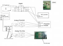
That won't work.
If you look at the dual 18 V xfmr, the lines need to be connected as follows for both the PGA2320 and The Wire power supplies (which connect to the xfmr in parallel):
AC
GND
GND
AC
It's OK to connect the windings at the center tap; you can use that as a star ground.
To make that clear, each PSU needs both 18V~ secondaries.
I think digital part of PGA2320 and its MCU controller should be fine without any grounding (If I'm profoundly mistaken maybe then I need another transformer with dual secondaries, or center tap like 9V-0-9V). As I read elsewhere grounding is important for analog and bipolar PSU.
Anyhow, as long as center tap from dual secondaries is connected to analog PSU. And there is a recommendation in TexasInstruments datasheet for PGA2320.
And it clearly states:
Anyhow, as long as center tap from dual secondaries is connected to analog PSU. And there is a recommendation in TexasInstruments datasheet for PGA2320.
And it clearly states:
PRINTED CIRCUIT BOARD LAYOUT GUIDELINES
It is recommended that the ground planes for the digital
and analog sections of the printed circuit board (PCB) be
separate from one another
Last edited:
There are some reasons to use NEMA box. Plastic is easy to work with and ground is not a problem as I am planning to do just as you suggested. Also thinking of connecting the transformer secondaries in center tap scheme for the analog supply. This way ground plane should be ok.
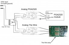
This drawing has a typo error. The polarity dots and the terminal numbers are mixed-up.
dual secondary for center tap
more like this mate. if dot means beginning of a winding, then dot = white wire on the dodgy pic I have made up. black from first to second is negative, green ground and red positive
more like this mate. if dot means beginning of a winding, then dot = white wire on the dodgy pic I have made up. black from first to second is negative, green ground and red positive
Attachments
Last edited:
- Status
- This old topic is closed. If you want to reopen this topic, contact a moderator using the "Report Post" button.
- Home
- Amplifiers
- Headphone Systems
- ODAC + PGA2320 + The Wire = The ultimate budget headphone system