On the finish line
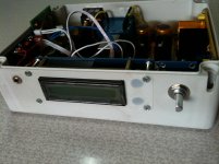
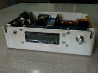
Some progress on the project was made for past two days. The little problem left to be solved is bolts to mount the pcb's inside the enclosure. I have bolts and nuts but some bolts are short for my purpose. In a few days will get those. As for the project itself: both trafos, iec, power switch are all in place wired up. There is very little left to make this box sing.")
Some progress on the project was made for past two days. The little problem left to be solved is bolts to mount the pcb's inside the enclosure. I have bolts and nuts but some bolts are short for my purpose. In a few days will get those. As for the project itself: both trafos, iec, power switch are all in place wired up. There is very little left to make this box sing.
Attachments

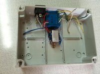
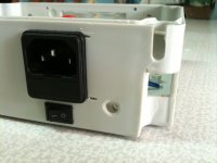
If you are planning on working inside the box while its live, or even if you aren't, then I would suggest putting some heatshrink over the terminals on the IEC socket.
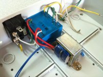
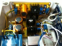
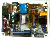
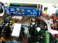
I am a bit confused about primary connections on your transformers. Looks like green + white becomes green + yellow somewhere between transformer and IEC socket. I'd personally prefer to connect each transformer to the IEC socket rather than parralleled how you have them. I'd also put some heatshrink ove the live terminals on the pcb mount transformer for safety if you are working / troubleshooting things while they're installed in the case. Working in a tight area means you're more likely to bump things inadvertently and exposed live wires are not what you want in that situation.
I am a bit confused about primary connections on your transformers. Looks like green + white becomes green + yellow somewhere between transformer and IEC socket. I'd personally prefer to connect each transformer to the IEC socket rather than parralleled how you have them. I'd also put some heatshrink ove the live terminals on the pcb mount transformer for safety if you are working / troubleshooting things while they're installed in the case. Working in a tight area means you're more likely to bump things inadvertently and exposed live wires are not what you want in that situation.
ditto to what hochopeper has said above; at the moment its needlessly dangerous and I see no benefit to connecting the transformers like that either, the mess of wiring over on the right to turn dual secondaries into a center tapped secondary; is it even needed? cant you just connect them directly together with a small stripped section and connect one wire from that?
at the moment its a bit of a deathtrap and does not showcase safe building techniques, if you are going to have a thread showing people how you did things, it has to be safe. I also cant se what happens with the yellow from the IEC turning into white, but going by the rest it probably isnt insulated.
you have also made no effort to follow colour codes. you even have the right colours there to do it, youve just used them incorrectly. thats not a huge deal if its just for you, but I dont get it and if you ever sell it you should really make that right.
Thank you hochopeper and qusp for suggestions. Will work on exposed terminals with shrink tube to make it safe. As for the colours: they are pretty random.
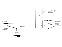
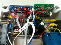
From IEC wires go to switch and then to primary of big trafo. Primary of the small trafo are connected there as well. So it means primaries of both trafos are connected, is this troublesome? Is there a difference if I will connect them to IEC and switch terminals?!
You can see the wiring scheme in attachment. BTW Mr. qusp you suggested in post #20 to wire secondaries just like I did in picture.
Attachments
the wiring is correct on the secondaries, I recommended that initially when I thought you had a normal TX, not a PCB mount one. theyre correct but they are just too long and you can achieve the same connection by connecting the 2 pins together and then one from that. you dont have to do that, you would go a long way just by making the colours consistent. twisting the pairs and generally neatening it up, trimming a bit shorter would help too, given you only have a small case. grab a cheap bag of zipties, you wont believe how handy they are.
really it would be best to connect the 2 to the IEC separately, there isnt much current here so its not a huge deal.
that part is just not such a problem, the mains stuff is the dangerous bit.
definitely insulate the IEC terminals, the switch and the transformer primary pins, especially with them pointing up like that. pick a scheme on the wiring and make it consistent. with what colours you have there, I would use green for ground, red for live (maybe yellow for the center tap) and white for neutral, but maybe look up your regional coding. given you dont seem to have ground connected on the IEC, dont use green till after your power supply so it actually signifies ground
Thanks qusp for clarification on this. Definitely will take care of exposed terminals and work around with shrink tubing here. Aslo will reconnect the small trafo to IEC socket and change the center tap at the dual secondary trafo for small connection between center pins and a wire attached to them just as you suggested in last post. Also will try to arrange wires with help of zipties.
Really hope other people won't make such a noobish mistakes as I did.
P.S. Stay tuned as the finish of this project is nearby.
Really hope other people won't make such a noobish mistakes as I did.
P.S. Stay tuned as the finish of this project is nearby.
Little update. Assembled all parts today and turned on the device. First off cheked DC offset. All seemed fine with offset less then 3mV on one chanel and around 0.5mV on the other. Turned on Foobar with Wasapi and ODAC as main output. Set it to 24 bit. Pluged in cheap headphones to test this setup and had sound only on the right chanel. Left was dead quiet.
Suddenly I cheked with DM ground for digital and analog parts and what do you know... they are common. It is bad. TI clearly states for PGA2320 that digital and analog grounds must be separate. Maybe it causes the problem. It is strange because I don't see where I could connect them. Analog ground goes from center tap of dual secondary trafo. Digital supply has his own trafo.
Maybe another source of problem is bad connections. I double cheked them, all seems fine with DM right up to hedphone jack from the DAC line out.
Maybe an error with The Wire amp. And here I cheked it with DM at least 4 times. All values seem just fine and all connections are good.
Need help to get rid of common ground for PGA2320. Suggestions are more then welcome.
Suddenly I cheked with DM ground for digital and analog parts and what do you know... they are common. It is bad. TI clearly states for PGA2320 that digital and analog grounds must be separate. Maybe it causes the problem. It is strange because I don't see where I could connect them. Analog ground goes from center tap of dual secondary trafo. Digital supply has his own trafo.
Digital and analog ground (planes) MUST be connected together, SOMEWHERE. There will normally be a split in the groundplane running under the PGA chip, with a single joining point. I looked at the picture of the module you have bought, but I can't see any groundplane at all.
Whatever, this is not the cause of the missing channel.
Are you sure that the uProc is turning up both channels?
Oh, my bad. I've reread the TI datasheet on PGA2320. And the separate ground planes are required only on the PCB where PGA module is situated. And you are right digital and analog planes must be connected. I have tested ODAC with speakers and it works 100%. The problem could be only with PGA or the Wire amplifier itself.
Will update soon after troubleshooting.
Will update soon after troubleshooting.
Checked another time with DM for shorting between chanels and ground. All seem fine here. Another time pluged in speakers to ODAC line out and it plays good for both chanels. Checked headphones, they have both chanels working normal with other devices.
Connected ground at center tap to ground from digital regulator board. BTW the sound from right chanel is good without any problems. And no noise or hiss whatsoever even with PGA set to +4dB volume level. The only problem is the missing left chanel.
I think for the next step will solder a connector directly to PGA2320 board an check if the problem is here. If something will be wrong or just like previous the left chanel will be missing. Then Will try some analog potentiometer in middle of ODAC and amp or will solder ODAC and The Wire amplifier together. This way the problem should be clear. Whether it is PGA or amp problem.
Happy to report that I found the problem. It was my lack of attention when redrawing the scheme of PGA2320 module before soldering things up. Accidentely mixed input and output pins for the left chanel. And I think it caused the problem. Connected ODAC to amp directly and both chanels playing loud and clear.
This weekend is busy so wait for update on Monday or Tuesday.
This weekend is busy so wait for update on Monday or Tuesday.
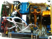
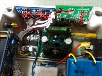
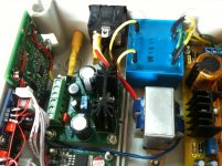
Here are some teaser photos of beta version. There is a little mess with wires but I didn't want to arrange them nice and tight without hearing the device playing music 100% without any problems.
Next week after resoldering work will try my best to manage the wires inside this small case. Upcoming project is restoration of vintage orthodynamic headphones Elektronika TDS-5m to make a sweet company for such a nice combo.
Next week after resoldering work will try my best to manage the wires inside this small case. Upcoming project is restoration of vintage orthodynamic headphones Elektronika TDS-5m to make a sweet company for such a nice combo.
Attachments
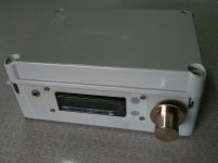
Hello guys. This weekend had some spare time so you can guess what it was used for. The problem was fixed fast with just resoldering two wires. Now I am happy to report that project is finished and works flawlessly!
It was quite a time since first bits and components where ordered. It also took long time for shipping and finding enclosure. And of course general lack of time.
Unfortunately I have no good headphones at this time and my vintage orthodynamics TDS-5m need some modding to sound their best. But I must admit that sound is very clean and detailed even on crappy headphones. With TDS-5m in stock form sound is even better but it will improve with proper damping, new pads and recabling. I am really happy with the sound and anxiously awaiting to get my hands on TDS-5m and treat them like they deserve.
Here are some pictures taken with iPhone. Next week will try to make some high quality photos.
General review and impressions will be some time after modding TDS-5m. Few weeks or so will do.
Please feel free to ask questions. Any suggestions are welcome.
It was quite a time since first bits and components where ordered. It also took long time for shipping and finding enclosure. And of course general lack of time.
Unfortunately I have no good headphones at this time and my vintage orthodynamics TDS-5m need some modding to sound their best. But I must admit that sound is very clean and detailed even on crappy headphones. With TDS-5m in stock form sound is even better but it will improve with proper damping, new pads and recabling. I am really happy with the sound and anxiously awaiting to get my hands on TDS-5m and treat them like they deserve.
Here are some pictures taken with iPhone. Next week will try to make some high quality photos.
General review and impressions will be some time after modding TDS-5m. Few weeks or so will do.
Please feel free to ask questions.
Any suggestions are welcome.Attachments
Last edited:
"Feel free to ask questions"
Okay, you said it!
What's the total cost of the project?
Is it possible to skip that display? I don't see the need for it.
Is it possible to put another 6.3mm jack on the backside and make it possible to switch between the two without any sound quality losses?
Are all parts available in Europe?
Any surface mounted devices that has to be soldered?
Can any of the parts be soldered by myself to save some money? Time is not a problem.
Will this amplifier be suitable for powering a pair of Denon AH-D2000?
Will you do any measurements?
Hi Rullknufs, you are welcome.
1) It was discussed in post #34 but in two word it totals around 300$ (without shipping cost for all components that can vary in different countries but in my case was around 40-50$ total ) and gross would be around 350$ but this amount can be bigger if you put more expensive supplies, connectors, trafos, MCU, PGA and other components.
2) Yes. Please refer to question 6) and here is an example here
3) In near future I plan to put another 6.3mm jack at the front panel without aby swithes just in case of using 6.3mm plug headphones but of course you can put dpdt switch for selection or you can use a relay with this MCU. It is a matter of taste.
4) Yes. I live in eastern Europe, country name is Moldova. I have used ebay as most handy method in my case. But keep in mind there are a lot of fake IC's and cheap crappy quality chinese stuff. There are distributors like mouser, farnell and others but they have bigger shipping cost.
5) Yes. OPC's The Wire amplifier is all SMD except the power capacitors and you will need at least some basic soldering skills. I did soldered this amplifier being with SMD for the first time. And only had at hand big and uncomfortable iron and it was a PITA to solder this tiny amplifier. All went fine and I am happy now and sure that can handle another project of this kind without major difficulties. Don't want to scare you just a safe warning to protect you from big disappointment.
6) Yes. You can solder power supply if you have necessary parts. And if money is a concern for you then you can put a simple stereo potentiometer in place of a PGA2320 solution like I did. It will save you good money. Minus one bipolar supply, one single 5V regulator, small trafo and PGA module with MCU. All these can be replaced with a simple pot if you wish. I just wanted some exotic and a volume control to match the quality of ODAC and The Wire amplifier.
7) Believe me this little beast can drive almost any headphones to ear splitting levels that can cause permanent hear loss. I have low sensitivity 100 Ohm vitage orthodynamic headphones and it drives them a lot louder then I would ever listen to. D2000 won't be a problem for this bad boy.
8) It is a good question. With regret I have no measuring equipment at home and have no access to measuring equipment around. If there will be a chance to get access to a decent measuring equipment or at least a high grade scope then possibly I could do some measurements. Programs on PC like RMAA in conjunction with cheap interfaces like E-Mu 0404 or M-audio fast Track don't give honest results and there are articles at the internet covering this aspect. Also don't see a lot of sense in doing measurements. ODAC is measured by NwAvGuy with dScope III, The Wire is measured by OPC with Audio Precision system and for the PGA2320 please refer to the datasheet.
Best regards
Last edited:
Hi Rullknufs, you are welcome.
1) It was discussed in post #34 but in two word it totals around 300$ (without shipping cost for all components that can vary in different countries but in my case was around 40-50$ total ) and gross would be around 350$ but this amount can be bigger if you put more expensive supplies, connectors, trafos, MCU, PGA and other components.
2) Yes. Please refer to question 6) and here is an example here
3) In near future I plan to put another 6.3mm jack at the front panel without aby swithes just in case of using 6.3mm plug headphones but of course you can put dpdt switch for selection or you can use a relay with this MCU. It is a matter of taste.
4) Yes. I live in eastern Europe, country name is Moldova. I have used ebay as most handy method in my case. But keep in mind there are a lot of fake IC's and cheap crappy quality chinese stuff. There are distributors like mouser, farnell and others but they have bigger shipping cost.
5) Yes. OPC's The Wire amplifier is all SMD except the power capacitors and you will need at least some basic soldering skills. I did soldered this amplifier being with SMD for the first time. And only had at hand big and uncomfortable iron and it was a PITA to solder this tiny amplifier. All went fine and I am happy now and sure that can handle another project of this kind without major difficulties. Don't want to scare you just a safe warning to protect you from big disappointment.
6) Yes. You can solder power supply if you have necessary parts. And if money is a concern for you then you can put a simple stereo potentiometer in place of a PGA2320 solution like I did. It will save you good money. Minus one bipolar supply, one single 5V regulator, small trafo and PGA module with MCU. All these can be replaced with a simple pot if you wish. I just wanted some exotic and a volume control to match the quality of ODAC and The Wire amplifier.
7) Believe me this little beast can drive almost any headphones to ear splitting levels that can cause permanent hear loss. I have low sensitivity 100 Ohm vitage orthodynamic headphones and it drives them a lot louder then I would ever listen to. D2000 won't be a problem for this bad boy.
8) It is a good question. With regret I have no measuring equipment at home and have no access to measuring equipment around. If there will be a chance to get access to a decent measuring equipment or at least a high grade scope then possibly I could do some measurements. Programs on PC like RMAA in conjunction with cheap interfaces like E-Mu 0404 or M-audio fast Track don't give honest results and there are articles at the internet covering this aspect. Also don't see a lot of sense in doing measurements. ODAC is measured by NwAvGuy with dScope III, The Wire is measured by OPC with Audio Precision system and for the PGA2320 please refer to the datasheet.
Best regards
Okay, a bit pricier than I thought. How much would it be in euros?
Money is not an issue really but I'd like to keep it somewhat cheap since I'd like to spend my money on other hi-fi stuff as well (building two audio amplifiers at the moment and planning a new speaker build).
I'd like to have all the connections on the backside, and analog inputs if possible. Also an output for headphones (to keep it tidy in the front). And on the front the volume pot and an extra headphone output if I have some headphones with shorter cable. And maybe some kind of switch between the two?
I think I might be able to solder the amp. I've soldered some surface mounted stuff on my previously mentioned audio amplifiers but I don't know if they work yet, hehe
The Wire seems to have to few parts as well so if I break something I guess it wont be that expensive to buy new, and besides I have a friend who has several drawers full of surface mounted parts and I can get a few for free if I need.What are the necessary parts for the power supply? Going with a simple stereo pot seems like a good idea since I want to keep it simple, tidy and clean
How much would this reduce the total cost?Rullknufs, using a simple potentiometer will reduce the cost by around 95$ cutting down the total gross price (with shipping included) to around 250$ or 200€.
You can put connectors as you wish. Do it for your own needs.
For the power supply I can suggest a simple LM317 and LM337 combo. Nothing fancy here and it isn't necessary as this LME49990 and LME49600 have outstanding PSRR and CMRR. You can build the scheme given in datasheet or google.
You can put connectors as you wish. Do it for your own needs.
For the power supply I can suggest a simple LM317 and LM337 combo. Nothing fancy here and it isn't necessary as this LME49990 and LME49600 have outstanding PSRR and CMRR. You can build the scheme given in datasheet or google.
- Status
- This old topic is closed. If you want to reopen this topic, contact a moderator using the "Report Post" button.
- Home
- Amplifiers
- Headphone Systems
- ODAC + PGA2320 + The Wire = The ultimate budget headphone system