Its when you drop a SMD part in your shag rug!!!
LOL
Alex
Haha that's why you order spares
")
...or work above a wood floor.
Congrats on the build. Your SMD soldering looks fantastic for a first timer. Wait til you get to 0603 and smaller. It ups the ante a bit.
I received a nice bag of goodies today... 2x OPA827 and 2x OPA1641. Gonna pull the OPA140s and give one pair a try.
Congrats on the build. Your SMD soldering looks fantastic for a first timer. Wait til you get to 0603 and smaller. It ups the ante a bit.
I received a nice bag of goodies today... 2x OPA827 and 2x OPA1641. Gonna pull the OPA140s and give one pair a try.
On second thought after replacing the OPA140s with OPA1641s I still get the higher voltage on Pin 2 of IC2. I think it's a little bit lower this time around. Still higher than 10mV. I think I'm going to try replacing the 49600 at IC2 and see where that gets me. Guess I'll move on to another project for the time being.
On second thought after replacing the OPA140s with OPA1641s I still get the higher voltage on Pin 2 of IC2. I think it's a little bit lower this time around. Still higher than 10mV. I think I'm going to try replacing the 49600 at IC2 and see where that gets me. Guess I'll move on to another project for the time being.
The OPA1641s don't have the same super-low input offset voltage that the OPA140, OPA827, and AD8610 do. I'm sorry I forgot to warn about that, I had forgotten about it myself. They are spec'ed at up to 3.5mV = 3500uV DC offset. But the output should not be all the way up at 10mV if the input on R1 is zero to ground. Please PM me when you dive into working on it again. Lets see if we can get this one figured out. One more thing to check is that all the connection pins are going into the U3 and U4 sockets on the O2 board. The pins on the inner side by the O2 power supply capacitors are hard to see without a flashlight shining in there. I've had one instance where one pin didn't make it into the socket.
Last edited:
Well it looks like I am having a problem with the relay again. The amp played perfectly fine all day yesterday both on AC and battery power and this morning I was listening to some music and the relay started switching on and off rapidly. It does it both on battery and AC power. Any ideas?
I found something that may be causing the problem. When I was installing the booster board and ran the wire from JP6 to R8(O2 pcb) I had remove and reinstall R8 since I had it mounted tombstone style with the end I needed to attach JP6 to face down. When I desoldered R8 it looks like I may have damaged the trace that goes from R4 to R8(O2 pcb). I soldered in a small piece of wire to repair the trace and so far so good the amp is playing normally again. I'm keeping my fingers crossed that my fix will solve the problem but only time will tell.
I found something that may be causing the problem. When I was installing the booster board and ran the wire from JP6 to R8(O2 pcb) I had remove and reinstall R8 since I had it mounted tombstone style with the end I needed to attach JP6 to face down. When I desoldered R8 it looks like I may have damaged the trace that goes from R4 to R8(O2 pcb). I soldered in a small piece of wire to repair the trace and so far so good the amp is playing normally again. I'm keeping my fingers crossed that my fix will solve the problem but only time will tell.
Good, that might be it. Also lets try a couple of more things. I'm going to send you a replacement U2 chip for the O2 board. There have been some bad ones that have caused some strange O2 problems over the last couple of years. I'm also going to send a through-hole resistor. If the new U2 doesn't solve it, then try unsoldering that wire from R8 and instead solder it temporarily to one end of that resistor, then solder the other end of the resistor to the end of C16 closest to the edge of the board, as below. That changes the relay circuit from "no turn-off thump" to just "reduced turn-off thump". And if that fixes things it will provide some more info. Note: don't connect that wire to C16 though without the (47K to 100K) resistor in series to limit the current.
The relay circuit essentially gets told what to do by the O2's power management circuit. If the O2 PM circuit is have some fast transient troubles it can show up in the relay circuit.
I'll get that stuff in the mail today.
Attachments
Last edited:
Fsatsil - also remember that while waiting for this stuff to arrive in the mail you can convert your unit back to an O2 by just unsoldering the 3 booster board wires, unplug it, and plug back in the 2 NJM4556A chips.
It is entirely possible for the U2 chip to have a problem that isn't showing up as a standard O2, but does show up when the relay is added. The relay circuit essentially can be "amplifying" an existing timing problem in that O2's PM circuit. Changing that U2 chip is a good place to start.
It is entirely possible for the U2 chip to have a problem that isn't showing up as a standard O2, but does show up when the relay is added. The relay circuit essentially can be "amplifying" an existing timing problem in that O2's PM circuit. Changing that U2 chip is a good place to start.
Last edited:
I've been listening to the amp for the last few hours and it has been working fine so hopefully my fix worked. I have a spare U2 chip and spare resistors so you don't have to mail them to me though I really do appreciate the offer If the relay starts to act up again I will try swapping in another Lm2903. While I had the amp apart I also drilled some holes in the front panel for the LEDs
If the relay starts to act up again I will try swapping in another Lm2903. While I had the amp apart I also drilled some holes in the front panel for the LEDsAn externally hosted image should be here but it was not working when we last tested it.
While I had the amp apart I also drilled some holes in the front panel for the LEDs
I like how those LEDs turned out! The LEDs alone say a whole lot about what is going on. They are after the mosfets, one per rail, so if both are on and they are about as bright you know that the mosfets are on and both power rails are up and doing their thing.
I've sent the chip and resistors anyway, one can never have too many O2 U2's on hand.
Hopefully the trace repair will take care of it. I'll study the circuit a bit more tonight and see if I can spot anything I may have missed there too.I tried adding a 100k resistor in series with the jp6 wire and it's working fine. I will let you know if the relay starts acting up again but hopefully the problem has been solved. Thank you for your help ADGR
. Thank you for your help ADGRAn externally hosted image should be here but it was not working when we last tested it.
Last edited:
I tried adding a 100k resistor in series with the jp6 wire and it's working fine. I will let you know if the relay starts acting up again but hopefully the problem has been solved
Nice job with heat shrink tubing on the end!
Looks like I may have removed a resistor that I shouldn't have between the V3.0 and V3.1 boards, which may be the cause of the relay issue Fsatsil ran into. If this turns out to be the case I'll send resistors to everyone with V3.1 boards.
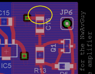
The resistor goes where the photo shows, just in series with the long wire going out to the O2 board. None of this is in the audio path, just the relay control circuit.I think I found my issue by looking at Fsatsil's pix. I didn't realize that R6 and R7 are not supposed to be soldered in a parallel position to C6, but perpendicular to C6. Guess I was moving too quickly. In the meantime, I ruined my 49600 by accidentally breaking off pin 2. I was grounding Pin 2 to test if the 49600 was working or not. After replacing U2 and swapping positions for R7 and R6 let's hope things are looking up for this project.
Here's a pic of my mistake...
Here's a pic of my mistake...
An externally hosted image should be here but it was not working when we last tested it.
An externally hosted image should be here but it was not working when we last tested it.
Last edited:
I think I found my issue by looking at Fsatsil's pix. I didn't realize that R6 and R7 are not supposed to be soldered in a parallel position to C6, but perpendicular to C6. Guess I was moving too quickly. In the meantime, I ruined my 49600 by accidentally breaking off pin 2. I was grounding Pin 2 to test if the 49600 was working or not. After replacing U2 and swapping positions for R7 and R6 let's hope things are looking up for this project.
Good find! That would explain what you measured. Your inverting pin on IC1 essentially wound up floating, since the loop was broken and C5 would have blocked any DC feedback. So that would have just left the O2's input to the IC1 non-inverting pin, which would have pegged the output of IC1 up to the positive rail - what you measured.
The Part ID diagram out on the project's Google Drive link is a good thing to review for those close-spaced parts:
https://drive.google.com/folderview?id=0B67cJELZW-i8NUdCREFQZ2F0Mmc&usp=sharing
I have circles around the parts and their part numbers to help out with the ID. I will add the orientation of these two resistors to the "things to watch out for" list in the build in the build instructions! If I do another layout of the board I should move R6 forward about a 1/2 SMD resistor length so the pads wouldn't line up with R7 in the up-and-down direction anymore. Plenty of space on the board to do that too.
If you are going to order an LME49600 you might want to consider getting a couple of more OPA140s too. I had forgotten about that DC offset voltage issue with the OPA1641. The OPA140 or OPA827 would give you much smaller DC output offset, if you would be up for another round of Chip-Quicking.
The original OPA140 might actually still be good, but since it has been heated quite a bit I would suggest tossing the originals and putting in new ones.Just an update, my booster board has been working perfectly since repairing the trace on the O2 pcb and installing a 100k resistor in series with JP6. I just measured the dc offset and one channel is .2mV and the other is so low my Fluke77 can't even measure it! That's quite an improvement over my stock O2 which was around 4-5mV!
. I just measured the dc offset and one channel is .2mV and the other is so low my Fluke77 can't even measure it! That's quite an improvement over my stock O2 which was around 4-5mV! An externally hosted image should be here but it was not working when we last tested it.
An externally hosted image should be here but it was not working when we last tested it.
When running on batteries what voltage should the batteries run down to before the O2 shuts down? Mine is shutting down when the batteries get to 8.2V which seems kind of early. The batteries I'm using are standard Energizer Nimh 8.4v/175mAh
The batteries are likely to be one problem. I'll send you a pair of the standard Tenergy 250mAhr NiMH for the O2. In fact, I should add that to the "disadvantages" list in the build instructions. The smaller 200mAhr batteries or below are probably not going to be a good match with the booster board installed. With the booster board the combination draws slightly more current than the standard O2 and will shorten battery life.
As for the cutoff voltage, the details are here at the bottom of a post I did way back when in the O2 mods thread:
http://www.diyaudio.com/forums/head...rc-diode-cap-heatsink-mods-3.html#post3194263
6.33Vdc with the standard batteries. Try that new U2 when it arrives and see if it makes a difference. Also, if possible, measure the voltage across your O2's red LED and see what you get. The easiest way may be to temporarily solder a couple of small wires to the red LED pads on the back of the O2 board to run out to your meter leads. NwAvGuy uses that red LED as a voltage reference for the O2's comparator circuit.
Hey that is good news the 100K resistor solved your relay problem!
I had to chuckle a bit over that 0.0mV DC output offset reading.
That is real! It is probably around 20 microvolts or so, less than the meter can read. It is possible that your OPA140 in the other channel got heat or static damaged a bit during the install. At the very most they should only be around 0.12mV, but usually just 20 - 30uV or so. One of these days you might want to try replacing it and see if a new one will bring that DC offset down to 0.0mV on that channel too. You can get those out by carefully cutting each of the 8 chip leads close to the chip body with flush cutters, then going back with solder wick and cleaning the remaining chip leg off of each of the 8 pads. Or if you have some Chip-Quick that does the job too.
Last edited:
Fsatsil - also, on that O2 battery cutoff voltage measurement, to be accurate that has to be done in the 30 minutes or so before the batteries cut off. Once the O2's mosfets have cutoff the battery load, the battery voltage will jump up a certain amount, so measuring after cutoff won't give an accurate reading. You may already be measuring before cuttoff, but the best thing to do is just leave the voltmeter on one of the batteries once it gets within an hour or so of typcial cutoff time. Then write down the battery voltage ideally every 15 minutes until it cuts off. There will probably be a fairly sharp drop in battery voltage that that 15 minutes. Won't be a linear drop.
Thanks AGDR I received your package in the mail today and it is greatly appreciated. I've been using those same Energizer batteries since I first built the O2 a few years ago so it's probably time for some new batteries anyways. Let me know how much those Tenergy batteries cost and I'll paypal you the money.
. I've been using those same Energizer batteries since I first built the O2 a few years ago so it's probably time for some new batteries anyways. Let me know how much those Tenergy batteries cost and I'll paypal you the money.- Home
- Amplifiers
- Headphone Systems
- O2 headamp output booster PCB