I have some Wouxuns 144/440 and looked at them on my Aeroflex 1200s spectrum analyzer , very clean signal.
Wouxun Electronics Co., Ltd , Professional Two Way Radio Manufacturer
I forgot that I have a Wouxon KG-UV1 dual bander ( 144 / 220 Mhz ), but it does not look to be certified to part 90.
Here is a list of the grantee codes for anyone that wants to search the database to see if their radio is "legal" or persona non grata:
FCC Part 90 Compliance - Miklor
It looks like most of my cheapos are legal, including the Leixin ( sp ? ) mobile dual bander I bought for $50 USD when eBay ran another flash sale a few weeks ago ....
Win W5JAG
Maybe specs for 220 are different but probably would make a great band for commercial interest with deep pockets.
I'm surprised we still have 6 meters.
Hi George,
I had a continuous battle with the low capacitance cable craze where they were applied to the turntable. No one compensated for the lost capacitance! In fact, no one had even measured the input capacitance to the preamps either. So I would measure the turntable, and the preamp and then pad the input of the preamp for the recommended capacitive load from the cartridge manufacturer.
A really simple concept that was lost on most people in the "high fidelity profession". Most customers got it once I showed them. Sadly, most "upgrade" cable was very thick and impossible to work with. I did install a fair amount of Monster 300 series cables, and RG-58c/u for others who were high on an RF cable kick. At least these were compensated for and their cartridges tended to sound better.
-Chris
Don't know too much about the history of cable testing.
We noticed a difference immediately on changing out stereo cable from a tube line amp. It is medium z out.
My focus is on phase errors and TIM.
Monotonic tracks are no problem but the phase smearing is unacceptable on complex music.
Making up some RG62 stereo cable sets today for long term testing.
.
I'm surprised we still have 6 meters.
I made an advance trip to the holiday house over the weekend, and while driving up there, gave some serious thought to making the present project a 6 meter rig instead of a 20 meter rig.
I have almost nothing good to say about that LO I am using, other than that it is stable. Just leave the thing parked on the SSB calling frequency and wait for band openings ...
I've fooled with TX mixers the last few days. Whole shack smells like burnt up semi conductors.
Win W5JAG
measure the turntable, and the preamp and then pad the input of the preamp for the recommended capacitive load from the cartridge manufacturer.
I know that there is a small SMD cap across the input of my phono stage inside the TT base. I built it about 10 years ago and have no clue what it's value is, or how I got there. I also have a new cartridge, A Shure M97XE that I bought when they were discontinued. It wants 250 pF and 47K ohms, so I will change the parts whenever I get around to changing the cartridge.
The TT currently has an ADC Series II cartridge in it now, which I am happy with. Either I put it in there a lonnnnng time ago, or it's the original that came in, or was bought with the Technics SL-D2 that I bought around 1980 when a local Florida store was going out of business and selling stuff cheap. It wants 275 pF and 47K, so I'm not too far off if I did it right the first time.
My focus is on phase errors and TIM. Monotonic tracks are no problem but the phase smearing is unacceptable on complex music.
A fixed capacitance should not be a problem as long as it's not excessive and within the source's ability to drive it in a linear manner. Many plastics used in capacitors and cable dielectrics may not be totally linear in their dielectric VS voltage characteristics. Ceramics are definitely voltage dependent as are reverse biased semiconductors. These are the big hitters in the PIM and TIM distortion generator department, but it is possible that some Walmart grade cables are too. ALL cables will exhibit some capacitance change with movement and temperature variation.....
Early on in my engineering career at Motorola I was chasing down the loss of receiver sensitivity on a two way radio product when stuck in temperature chamber cranked to -40C. It turned out to be the cable. It's loss went up when it got cold. All testing was done with Teflon cables after that.
Did you review the mixer?
I dunno what's wrong. It's drawing too much current, and smoking SMD resistors and zeners. I hate to point blame at bad parts, since it is usually some mistake on my part, but I think I may be dealing with a bad chip.
Win W5JAG
Maybe it's time to string up a wire and connect up my 817.....if I can find it.
Will QSO some time!
220 are different but probably would make a great band for commercial interest with deep pockets.
Where do you think the bottom 2 MHz went.....into brown delivery trucks.
I've fooled with TX mixers the last few days. Whole shack smells like burnt up semi conductors......I dunno what's wrong. It's drawing too much current, and smoking SMD resistors and zeners
I may be known for melting vacuum tubes, but in truth I have fried far more silicon, GaAs, SiC and GaN than tubes in my electronics adventures. Much of that happened at Motorola while developing some broadband high power RF amps and the associated SMPS's.
Little SMD things smoke and make some stink. I went through a few hundred 2N7002's over the years, and plenty of SOT89 parts.
Fets fed by a power supply big enough to simulate a car battery burst into flames and make a lot of stink, so do tantalum caps.
A tantalum will spontaneously explode, even when operated well within its ratings, if used as the supply bypass cap feeding a TDMA (pulsed RF) transmitter. The ceramics of the day were piezoelectric. They didn't blow up, they just buzzed, cried and screamed at the TX rep rate. We had to balance the two kinds of caps to keep the flames and the noise down.
Discrete parts in a tube amp connected up to my 1KW @ 650 volt power supply just explode violently leaving only a stain on the PCB where the part was.
I have 817 too and have become expert on covert HF antennas.
I lost a battle with the Florida city I lived in over a TV satellite dish being used as a ham radio antenna. I was planning an attack on the distance record for an EME QSO on the 902 MHz ham band, when the city slapped a violation notice on my house for the antenna that had been there for over 10 years which was "grandfathered" and protected by PRB1. This escalated to the mayors office where he told me that he didn't care about PRB1, this was his city and he could do what he wanted. I then had two days to remove ALL antennas from my house including the Radio Shack TV antenna, or face a $200 per day fine. My lawyer explained that I could probably beat this in court, but it would cost me far more $$$$ than I could afford to risk.
A few years later a hurricane trashed the city and code compliance had bigger problems like crack heads setting up shop in abandoned houses, so I put up a wire antenna and played JT65 on 20 meters.
Now I have an acre and I am not in a city. I'm just down in a 300 foot hole.
I'm trying to make NE/SA602 work as a TX mixer. Should be dirt simple, good to go in about an hour or less, right?
The chip should draw 2 -3 ma, or so. I keep winding up with 30 - 50 ma. They draw the right amount of current for a few minutes, then the current jumps up, and parts smoke / stink. Worse, they won't even mix. I hooked the output to the FFT and all I see are the two inputs - no sign of any mixing products.
I doubt the chips are counterfeit, I bought them back in the 80's when Signetics brought them to market and they were the hot, new, thing. Likely they came from two different vendors, as one corpse has the original NE markings, and one has SA markings. Even with my luck, it seems inconceivable to me that I could manage to purchase, and then pluck out two bad parts from TWO different places and / or production lots. So, I don't think it is bad parts; the odds are just too long on that.
I'm doing something wrong, and I have absolutely no clue what it is. I'd like to sort this out just on general principle, even if I ultimately decide to use a different mixer, but don't want to kill more of these chips. The DIP version that I am using ( killing ) is a pretty expensive part these days. I don't have enough to be reckless with.
I hooked up an SBL-1 and looked at the output, and saw what I expected to see - lots of mixing products and the inputs attenuated relative to the primary mixer products. Not as much as I expected though - only about 20 db. It was a clip lead furball, and unmatched ports, so not drawing any conclusions. It was interesting to use the FeelTech as the signal source, and play with the input levels / wave shapes on the ports, and look at the effect on the output.
I might wind up using a passive mixer; I'm not that concerned about the signal loss.
On a brighter note : 10% off on eBay today! Load up on Banfengs!
Win W5JAG
10% off on eBay today! Load up on Banfengs!
I think I have caught my limit on cheap Chinese radios. I have one for each hand, and I don't need a walkie talkie to talk to myself.......I just wish that Ebay did the discount thing when I ordered the radio.
I spent some time digging around on Ebay hoping to find a deal on a dead HP spectrum analyzer that went beyond the limit of my current analyzer, 2.9 GHz. People want too much $$$ for dead junk, but the test equipment market fluctuates a lot depending on supply and demand. When someone dumps a bunch of stuff, even good stuff on the market, everything drops in price, especially dead stuff. I'm in no hurry, so I'll just keep looking......
gave some serious thought to making the present project a 6 meter rig instead of a 20 meter rig.
I have a consulting job lined up that will mean putting the finishing touches on my RF workbench and clearing the half finished PC from the digital bench, and doing a bit of cleaning up.
Once My RF bench is operational, I'll need to put up some antennas since there are zero signals in the underground basement, except for some strange carriers of unknown origin. I traced a dead carrier that just happens to be on one of the local 440 MHz repeater outputs to the Sony TV set in a bedroom. It puts out this signal when OFF and it goes away when turned ON! Some of the others are coming from the Comcast box.
I played with the Hack RF One a bit a couple of weeks ago. Mine is a cheap Chinese clone and an impulse purchase when Ebay offered 15% off. It is a very dirty transmitter with many spurious signals. The receiver also has plenty of spurious responses. Maybe it's time for me to cook up something that works good enough to be usable. There are plenty of frequency synthesizer chips out there that go well into the GHz region, so why stop at 6 meters?
I have absolutely no clue what it is. I'd like to sort this out just on general principle
I used that part years ago without issue, so I dug up the data sheet.....
Pins 1 and 2 are the RF input. They must NOT have any external path to ground or other voltage source, but may have a DC path between them, like an inductor or transformer secondary. Ditto the output pins, 4 and 5. The oscillator pins, 6 and 7 must likewise be AC coupled, connecting a DC voltage, or path to ground upsets the internal biasing scheme and can lead to unexpected results.
It doesn't look like there can be a DC path from 6 to 7 either, since that would short out the bias on an internal buffer transistor. These chips are also meant for rather low level signals. I don't know how hard you are driving it, but it's made for a receiver front end.
I used them for a simple narrow band FM receiver project back in the 90's maybe. I fed the output of an RF synthesizer chip into pin 6, which must be capacitor coupled. It may have to be attenuated a bit if the synth chip puts out a large signal.
DC supply voltage should be less than or equal to 8 volts. I probably fed it with a 7808 chip since these kind of chips usually work best near max spec....better IM, gain and sometimes noise figure.
I'm using the simplest configuration, just to get it up and running before I balanced the input and output, and didn't expect any issues ...
pin 1 for 9 MHz TX input AC coupled through a .01 SMD cap.
Pin 2 goes to ground AC coupled through a .01 SMD cap.
AFAIK, pins 1 and 2 are interchangeable
Pin 3 goes to gnd
Pin 4 is open
Pin 5 is 14 MHz output AC coupled through a .01 SMD cap
AFAIK, pins 4 and 5 are interchangeable - output can be taken balanced, or single ended; OK to leave one side of a single ended output open
Pin 6 is LO AC coupled through a .01 SMD cap
Pin 7 is open
Pin 8 ... power ... bypassed with a .01 SMD cap. DC input at auto electrical bus voltages ( 12 - 15 VDC ) through a current limit resistor, 470R, shunted with a 7.5 volt zener.
This should work without issue.
I considered the 9 MHz drive issue, the chip being an RX mixer, but I toasted the first chip before I ever applied any 9 MHz or LO drive. I was making sure the static voltages and current were correct before I proceeded further ...
I thought maybe the chip was oscillating somehow with the ports unloaded, and destroying itself, so I loaded the ports, except I left pin 4 open. Nope, not that, another chip gone ...
I am SPECULATING, that maybe my zeners are crap, and after a few minutes are failing and zapping the chip with over voltage faster than my meter can see. All a voltmeter will show is the voltage on pin 8 going from normal, to less than 1 volt.
After whatever event is occurring, removing the resistor, zener, and just applying a regulated 6 volts direct to pin 8 is not effective - the chip will draw 30 to 50 mils depending on the applied voltage, and will not mix - looks like the inputs go straight through to the output ...
SMD SA602's are cheap enough, and still in production, so I guess I'll try some of those with different zeners, or even a three terminal regulator to test my speculation.
This is about all I can think of.
Those AD831 boards are too expensive to risk a blowout using them for a TX mixer, but I thought I might also try some of those HP DBM chips. I have enough of those that I don't mind burning up a few.
Win W5JAG
Maybe it's time for me to cook up something that works good enough to be usable. There are plenty of frequency synthesizer chips out there that go well into the GHz region, so why stop at 6 meters?
Those of us in the wading pool will have to wait for the PCB's; 0805 or 1206, please ....
Win W5JAG
.... I am SPECULATING, that maybe my zeners are crap,
Good grief.
Looking through my order history at Mouser over lunch, I see that to replace the dubious stuff I had on hand, I bought a couple dozen each, of a half dozen types of low voltage Zeners, ON MY LAST ORDER LESS THAN A MONTH AGO, and that I had already completely forgotten about

My parts inventory management leaves an awful lot to be desired.
Win W5JAG
...After whatever event is occurring ...
Using the newly purchased zeners seems to have resolved the quick death issue.
.... Pins 1 and 2 are the RF input. They must NOT have any external path to ground or other voltage source ...
Everything I have looked at shows an unused input pin AC grounded through a cap. I have not tried leaving an unused input pin open, but I don't see it harming the chip to try that. There was a Radio Electronics article "Single Chip Frequency Converter" at the time it was introduced, that is basically an application note for the chip. I think it is on that N5DUX link as a pdf.
With my mediocre instrumentation, I need to put about 4 volts p-p on the LO port and the RF input port to be able to see anything on the FFT, other than the LO. These drive levels are way too high, but do not appear to damage the chip. At these levels, there are a slew of IM, harmonic, and mixing products in the FFT.
It looks like there is no cancellation of the LO when the output is taken single ended. It does look like there is some cancellation of the RF input, maybe 20 db or so, with single ended drive.
Unfortunately, the desired 14 MHz product is really low relative to the rest of the products at these levels.
.... since these kind of chips usually work best near max spec....better IM, gain ...
Interestingly, at these over drive levels, it looks like best IM performance with this SA612 chip as a TX mixer is at about 6.3 VDC
... but it's made for a receiver front end
And it may be a dead end as a TX mixer for this radio. With normal drive levels of about 2 volts p-p LO, and 200 mv p-p on the RF input, everything but the LO is down below the noise of the 8 bit FFT. I can hear the 14 MHz signal on the FT 817 by clipping a test lead to the IF output, and then gimmick coupling that to a rubber duck on the 817, but it is very weak, and below what I expected.
Or, maybe I'm wrong - and those excessive drive levels have damaged the chip ...
I think I will go ahead and try balancing the input and output and see what that does.
Win W5JAG
I have looked at shows an unused input pin AC grounded through a cap.
For SE drive you should have a cap to ground on the unused input. I should have said no DC path to ground. The 602 has internal biasing circuits. External DC path's mess those up.
I can't say why it doesn't work right, it's been 20 some years since I played with those.
will have to wait for the PCB's; 0805 or 1206, please ....
I'm surprised at what's happened to the size of some parts since I was away from SMD assembly for about 5 years. Things that I would need to make a radio have shrunk from small to where is it. How do you hand solder a SAW filter when it is the size of a 0603 chip cap, but has 8 pads on it? The multiple conversion plan that I have, and the ultra low phase noise LO generator both need saw filters, lots of them.
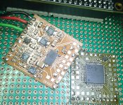
Don't panic; that's not much worse than the 24 pin + exposed pad ADC
on my self-etched board. Resistors & most caps are 0603, ADC has 0.5mm pitch.
(1MSPS 24 bit ADC LTC2500-32 to be married to a Beaglebone Black to
collect, store & FFT the samples.)
on my self-etched board. Resistors & most caps are 0603, ADC has 0.5mm pitch.
(1MSPS 24 bit ADC LTC2500-32 to be married to a Beaglebone Black to
collect, store & FFT the samples.)
Attachments
Last edited:
- Home
- Member Areas
- The Lounge
- No RF gear here?