Hello Miklos,
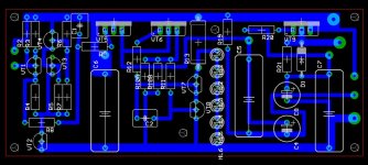
Very nice board.
Im interested how your board looks from the side of components, what technique do u use to sign the placements of parts?
Best regards
Goran
Hi Goran,
The half finished stereo board component side is visible in post #72.
I'm using the Eagle PCB program to make the board and assign designation numbers to the components. If that what you meant with your question.
Miklos
Hi Goran,
The half finished stereo board component side is visible in post #72.
I'm using the Eagle PCB program to make the board and assign designation numbers to the components. If that what you meant with your question.
Miklos
Hi,
I know my question was not so clear. Im using Eagle also, but i was asking about that side of the board which is without coper. On the picture of your board -post #72, there is no signed placement for the components from the upper side of the PCB.
Attachments
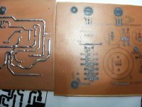
On the right side of the picture from my previous post i tried to implement the same aproach as for bottom side (coper side) to sign the placements for the components, but im not satisfied with the result as you can see. Maybe you know some other aproach (in the home conditions) for better signing for the component placements on the upper side of PCB.
Regards
Goran
Regards
Goran

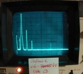
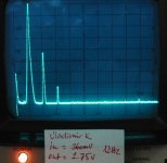
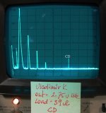
Finally I finished one channel of the amp and could measure it.
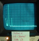
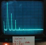
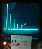
Here are the spectrums ,in the following order.
Output voltage: 760mV, 2.75V, 4V, 7.6V and 10V (clipping at 13V).
The source signal is a 1kHz Cd track, or a Sound Technology ST1500A (distortion test mode) oscillator, both clean to -90dB.
Here are the spectrums ,in the following order.
Output voltage: 760mV, 2.75V, 4V, 7.6V and 10V (clipping at 13V).
The source signal is a 1kHz Cd track, or a Sound Technology ST1500A (distortion test mode) oscillator, both clean to -90dB.
Attachments
Finally I finished one channel of the amp and could measure it.
Here are the spectrums ,in the following order.
Output voltage: 760mV, 2.75V, 4V, 7.6V and 10V (clipping at 13V).
The source signal is a 1kHz Cd track, or a Sound Technology ST1500A (distortion test mode) oscillator, both clean to -90dB.
Hello, Miklos
I am glad to hear that you have advanced in this project. The results of measurements are quite expectable, they provide some ground for good sound, but do not insure it.
Pay attention to output caps quality and power supply filtering, and I could predict that almost no industrial head phone amp could beat this device in listening comparison, at any price tag.
Have you managed to find the 2SK2199 transistors for this project?
Hi Vladimir, no I used a IRF610 there.
Hi Vladimir, no I used a IRF610 there.
For the output cap, I would propose paralleled Elna Silmic II 220...470uF x 63V, total capacity 1200...1500uF, plus polyprop shunt, 10...20uF.
First to PCB is connected the shunt, then twisted wire goes to electolytics cluster. The wire is copper or silver monowire, 0,5...0,8mm diameter, in teflon pipe.
For the PS rail, just on the PCB, use 4,7...10uF polyprop cap.
Before critical listening, the burn-in process must be done (white noise signal, resistive load, 24 hours).
I connected even loudspeakers to this schematics, it was quite possible to estimate sound.
Last edited:
Thanks for the advise Vladimir.
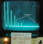
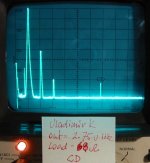
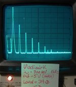
The above spectrum's are made without load.
The following ones are made with 39 and 68 Ohm's load.
The max output with 39 Ohm's load is 5V, it is better with 68 Ohm's.
The above spectrum's are made without load.
The following ones are made with 39 and 68 Ohm's load.
The max output with 39 Ohm's load is 5V, it is better with 68 Ohm's.
Attachments
I would like to note here, that the spectra measurements say only very small part of the story. They say about possible effect on the major components of the signal, that is about very small change of available at the output information. But they say nothing about complete losses of tiny components of input information, present at the input, but almost absent with bad amps at the output (in spite that bad amps can perfectly pass the major components). The reason of the losses of microdetails - the dynamical instability of the transfer function of the amp, due to thermal effects in semiconductors, due to effects in PS electrolytic caps, due to electromagnetic coupling, due to GNFB effects, etc. If the transfer function, being absolutely straight, is subject to a kind of "jitter", or thickening, the resulting sound is "dark" and "dull", "lifeless".
Believe, this schematics is for live-like sound, without losses of signal tiny components. These kind of non-linearity better not to improve, because of the risk of higher-order harmonics or losses of microdetails.
Believe, this schematics is for live-like sound, without losses of signal tiny components. These kind of non-linearity better not to improve, because of the risk of higher-order harmonics or losses of microdetails.
Last edited:
I believe in the spectrum's, as long as the amplifier has no negative feedback.
OK, it would be interesting at the end to hear about listening comparison, with an industrial headphone amp having much lower levels of harmonics.
My friends did it several times, with more than 1000 USD headphones and the best Perraux amps.
I don't have an industrial one, but have one or two tube ones with transformer output.
I will measure them and make a comparison listening test, but first I have to finish the second channel of yours. It will take some time. Regards.
Could you please post the harmonics spectrum for your tube headphone amp?
I guess, it will be a bit different, but again, one will never correlate spectrum with preferences of an experienced listener. Excuse me, Miklos, but it is very unusual to hear from a person, preferring tube amps, " I do believe in spectrums ". Than I wonder, what kind of spectrum do you prefer?
- Status
- This old topic is closed. If you want to reopen this topic, contact a moderator using the "Report Post" button.
- Home
- Amplifiers
- Solid State
- No NFB Headphone/Pre Amp